Chapter 1: Resistors
Jan 13th 2001 , Naveen P N
I begin the tutorials by assuming that you have basic knowledge about electricity like current ,voltage, charges etc.
A resistor is an electronic device that offers obstruction to the flow of electric current.
It can be defined as voltage per unit current through a conductor.
Resistance(R)= Voltage (V) / Current (I)
i.e. R=V/I
The unit of resistance is ohm denoted by W .
The circuit symbol of a resistor is:
 or
or 
In reality, a resistor looks somewhat like this:

It has no polarity (i.e. + and -) like a battery and can be connected either way in a circuit.
When you ask for a resistor at a store you need to specify 3 things:
- Resistance
- Power handling capacity ( wattage)
- Tolerance
The resistance is the value of the resistor in ohm Ω. It can also be in kiloohm (kΩ) or megaohm ( MΩ ).
Here 1kΩ = 1000Ω
And 1 MΩ = 1000kΩ
The power handling capacity of a resistor determines the amount of current that can be passed safely through it. It is specified in watt (W). The normal resistors that we use will have a ¼ W capacity. This means that if the resistance is 1kW and ¼ W , then the max. Current that can be passed through it is given by:

Where I is max. Current, W is the wattage rating, R is the resistance. For the 1kW and ¼ watt resistor,
W= ¼ = 0.25 W
R = 1kΩ
Hence I = 16mA (mA = milliamp = 0.001 amp) . This is the max. Current that can flow through this resistor.
The resistors are available in 1/8 W, ¼ W, ½ W , 1W , 2W and so on.
As the wattage increases the resistor’s cost tend to increase and they also get bulkier.
Tolerance is the extent to which the resistor value sways from the original value. You may think as to why the resistance value should change from the printed value? Well, we live in a world that is far from perfect and resistors are no exceptions. Their value changes mainly due to the change in temperature.
The tolerance values of commercially available resistors are usually ±5%, ±10% and ±20%, where the value indicates the % drift from the original value.
e.g. , if the resistor value if 1kΩ and has a ±10% tolerance, it means that the actual value of the resistor may be between 1kΩ ±10% i.e 1kΩ + 100Ω or 1kΩ – 100Ω i.e. 1.1kΩ to 0.9kΩ
How to identify the resistance value from color bands:
Hold the resistor as shown below:
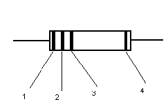
Three bands that are close together are to the left.
Then colors of:
Band no.1 signifies the 1st digit
Band no.2 signifies the 2nd digit
Band no.3 the multiplier.
Band no.4 the tolerance.
|
Band Color |
Band 1 and 2 |
Multiplier |
Tolerance |
|
Black |
0 |
1 |
– |
|
Brown |
1 |
10 |
1% |
|
Red |
2 |
100 |
2% |
|
Orange |
3 |
1000 |
– |
|
Yellow |
4 |
10,000 |
– |
|
Green |
5 |
100,000 |
– |
|
Blue |
6 |
10e6 |
– |
|
Violet |
7 |
10e7 |
– |
|
Grey |
8 |
10e8 |
– |
|
White |
9 |
10e9 |
– |
|
Gold |
– |
0.1 |
5% |
|
Silver |
– |
0.01 |
10% |
|
No Color |
– |
– |
20% |
For example:
Band 1 =Red
Band 2= Violet
Band 3= Orange
Band 4= gold
Resistance = 27 X 1000 = 27000ohm = 27 kΩ ± 5%
Band 1= Brown
Band 2= Black
Band 3 = Red
Band 4 = Silver
Resistance = 10 X 100 = 1000 ohm = 1k ± 10%
The standard values available commercially are have the first 2 digits: 1,12,15,22,27,33,39,47,51,56,68 or 82
Resistors in series and parallel: (added Jan 26th,2001)
Sometimes, resistor values other than the standard available values are required for a circuit. In such a case the required value is obtained by connecting a number of resistors either in series or in parallel.
Series Connection:
In series connection, the resistors are connected end to end as shown below:
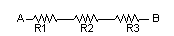
In such a connection, the total resistance between the terminals A and B is the sum of individual resistances.
i.e., Rab = R1 + R2 + R3
For example, if a 2.2K and 3.3K resistors are connected in series, the total resistance is 2.2+3.3 = 5.5Kohm.
Parallel Connection:
In parallel connection, the resistors are connected as shown below:
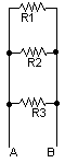
In such a case, the total or effective resistance between terminals A and B is given by:
1/Rab = 1/R1 + 1/R2 + 1/R3
i.e. the reciprocal of the effective resistance is equal to sum of the reciprocals of the individual resistances.
If there are only two resistors, the above formula reduces to:
Rab = (R1*R2) / ( R1+ R2)
e.g., if two 1K resistors are connected in parallel, the effective resistance is (1*1)/(1+1)= 1/2 = 0.5K=500 ohm.
Variable Resistors:
The resistors studied above are “fixed” type, i.e their value cannot be changed. There is another type of resistor called as the variable resistor whose resistance can be varied. They are called as “Potentiometers(pots)” or “Presets”.
A potentiometer looks bigger than a preset and is used for frequent variations. The preset is used for setting up or calibrating a circuit and once done is usually not touched often. A common example of a potentiometer is the volume control on your cassette player.
Usually all pots and presets have 3 terminals, the outer 2 are fixed ends and the middle terminal gives a variable resistance along with either of the other two.
The circuit symbol is:
3
1 2
2
The terminal with the arrow(3) is the variable terminal.
The terminals 1 & 2 are fixed.
The pots value is specified as the max. value of resistance it can provide. For example, if the pots value is 10K it means its resistance can be varied between 0 to 10K ohms.
In the above figure, if you use 1 & 2 to connect the pot. to the circuit,the resistance is fixed and equal to the max. value (in this case 10K ohm)
If 1 & 3 OR 2 & 3 are used , it provides a variable resistance from 0 to 10k as the pot’s shaft is rotated.
Formulae to memorize:
1) V=IR
2) W=I². R
3) R(series)= R1+R2
4) R(parallel)= (R1*R2)/(R1+R2)
Along with the introduction to resistors, I’ll present here a few basic symbols used in electronics:
1) _________
Denotes a wire or a connection.
2) 
This symbol denotes “Ground”. Imagine this as the common point of all connections in a circuit.
3) 
This denotes a battery. The upper (longer) portion is the + or positive terminal of the battery. The lower portion is the – or negative terminal of the battery.
4) 
Denotes a normal bulb.
by Naveen P N

To subscribe to newsletters click here.