PIC based Temperature Indicator & Control Circuit
Circuit description: This circuit displays the temperature of the surroundings and also the set temperature. The circuit can switch ON/OFF a heater based on the present temperature. Using a keypad provided the user can set the required temperature. The device will switch ON the heater if the room temperature is below the set temperature. It will switch OFF the heater when the temperature raises above the set temperature, and thus maintaining the room temperature.
The temperature can be set between 2degC to 99degC
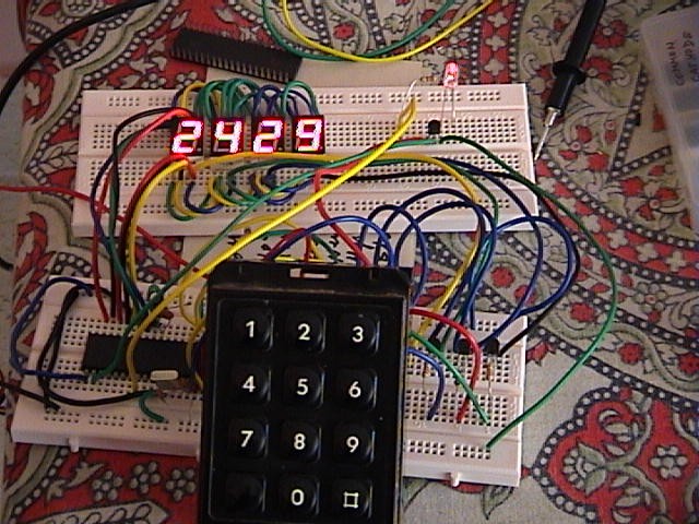
How to use? When the device is powered up, the display will show four digits. The first two digits (DIS1 & DIS2 in the circuit diagram) indicate the current temperature in Centigrade. The next two digits (DIS3 & DIS4 in the circuit diagram) shows the set temperature.
To set a temperature press ‘#’ in the keypad. This will clear the set temperature field (last two digits = 00) in the display. Enter the two digit temperature. The set temperature field will get updated. If the entered temperature is invalid (eg ‘##’) an error message(Er) is displayed in the last two displays. Based on the values of current and set temperature the device will switch ON/OFF the heater and will maintain the room temperature.
How does the circuit work?
The circuit uses a PIC to take input from keypad, display current and set temperature and also to measure the temperature. The transducer LM35 gives an electrical voltage based on its surrounding temperature. This voltage is analog in nature. This is converted into a digital code using the A/D converter present in the PIC. Using this information the software running inside the PIC can turn on/off a particular pin in the PIC. To display the set and current temperature a common anode seven segment display has been used.