
 On eBay Now...
STLINK-V3MINIE STM32 In-Circuit Debugger Programmer USB 2.0 High-Speed Interface For Sale

When you click on links to various merchants on this site and make a purchase, this can result in this site earning a commission. Affiliate programs and affiliations include, but are not limited to, the eBay Partner Network.

STLINK-V3MINIE STM32 In-Circuit Debugger Programmer USB 2.0 High-Speed Interface:
$35.14
STLINK-V3MINIE, In-Circuit Debugger And Programmer For STM32STLINK-V3MINIESTM32 Debugger/Programmer
Based On Arm Cortex-M STM32 32-Bit Microcontroller
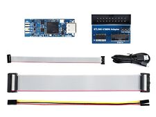
The STLINK-V3MINIE is a stand-alone debugging and programming tiny probe for STM32 microcontrollers, portable and easy-to-use. Onboard JTAG/SWD interfaces for communicating with STM32 microcontroller, also provides a virtual COM port for the host PC to communicate with the target microcontroller through one UART.
Features At A Glance- Tiny 15 mm × 42 mm stand-alone debugging and programming probe for STM32 microcontrollers
- Self-powered through a USB Type-C connector
- USB 2.0 high-speed interface
- Probe firmware is updatable through USB
- Support drag-and-drop Flash programming of binary files
- Two color LEDs: communication, power
- JTAG communication support up to 21 MHz
- SWD (Serial Wire Debug) and SWV (Serial Wire Viewer) communication support up to 24 MHz
- Virtual COM port (VCP) up to 15 Mbps
- 1.65 to 3.60 V application voltage support
Software SupportHardware Support
Support All STM32 Series MCUs With JTAG / SWD Interfaces
for reference only, STM32 MCU is not included.STLINK Series Selection GuideITEMV3MINIEV3SETV2JTAG/SWD APPLICATION APPLICATION VOLTAGEN/A1.65V~5.5V1.65V~5.5VSWV SUPPORTYES②DEBUG INTERFACEmultimulti③2LED INDICATORtwo colors④① ST-LINK/V2 and STLINK-V3MINIE support STM32 low-power devices.
② Only available for STM32 at present.
③ STLINK-V3SET features GPIO port besides the programming port.
④ Two colors LED indicates both power and communication.
Connection Example
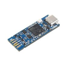
What's On Board
- USB Type-C connector
- Power LED indicator pad (LED is not soldered here)
- STM32F723 MCU
- BTB (board-to-board) card edge connector pads
- STDC14 debug connector
- COM LED Indicator
The LED is blinking red: the first USB enumeration with the PC is taking place.
The LED is red: the communication between the PC and STLINK-V3MINIE is established.(end of enumeration).
The LED is blinking green/red: data are being exchanged between the target and the PC.
STLINK-V3MINIE In-Circuit Debugger And Programmer For STM32
$45.49
STLINK-V3MINIE STM32 In-Circuit Debugger Programmer USB 2.0 High-Speed Interface
$35.14
![]()
Popular Tutorials
Alarms and Indicator Circuit diagrams- Power supply failure alarm
- Theft preventer alarm
- Rain Alarm
- A simple electronic buzzer
- Water Level Indicator with alarm
- Stereo Channel Selector
- Low cost intercom using transistors
- Infrared Head Phones
- Use the CD-ROM drive as a audio CD player without the computer
- Audio Visual Indicator for Telephones
- Ultrasonic pest repellent
- Charge Monitor for 12V lead acid battery.
- Wiper Speed Control
- Dome Light Dimmer for Cars
- Car anti theft wireless alarm.
- Control electrical appliances using PC
- Simple Analog to Digital Converter
- PC based Frequency Meter
- 7 segment rolling display using PC
- Electronic Scoring Game
- JAM(Just A Minute) Circuit
- Flashy Christmas Lights
- TV remote control blocker
- Light Flasher (blinking lights)
- Automatic Dual output Display
- Emergency Light
- Automatic Room Lights
- Running Message Display
- Automatic Speed Controller for fans & Coolers
- Soft Button type Motor Direction Controller
- Super simple stepper motor controller
- Discrete component motor direction controller
- Negative supply from single positive supply
- Self switching Power Supply
- Ultra low drop linear voltage regulator
- Car anti theft wireless alarm.
- Long range FM transmitter
- Remote control using VHF modules
- 40 meter Direct Conversion Receiver
- Remote control using VHF modules
- Remote control using telephone
- A simple Remote control Tester
- Clap Activated Remote
- Radio Remote Control using DTMF
- Ultrasonic switch
- Magnetic proximity sensors
- Dew sensor
- Color Sensor
- Metal Detector
- Optical toggle switch using a single Chip
- Telephone Ringer using 556 dual timers
- Two line intercom plus a telephone changeover switch
- Telephone line based audio muting and light on circuit
- Having secrecy in parallel telephones
- Telephone call meter using calculator & COB
- High Resistance Voltmeter
- A simple Remote control Tester
- Contactless Mains Voltage Indicator
- Zener Diode Tester