
 On eBay Now...
Tenma Model 72-1082 ATX Power Supply Tester For Sale
When you click on links to various merchants on this site and make a purchase, this can result in this site earning a commission. Affiliate programs and affiliations include, but are not limited to, the eBay Partner Network.

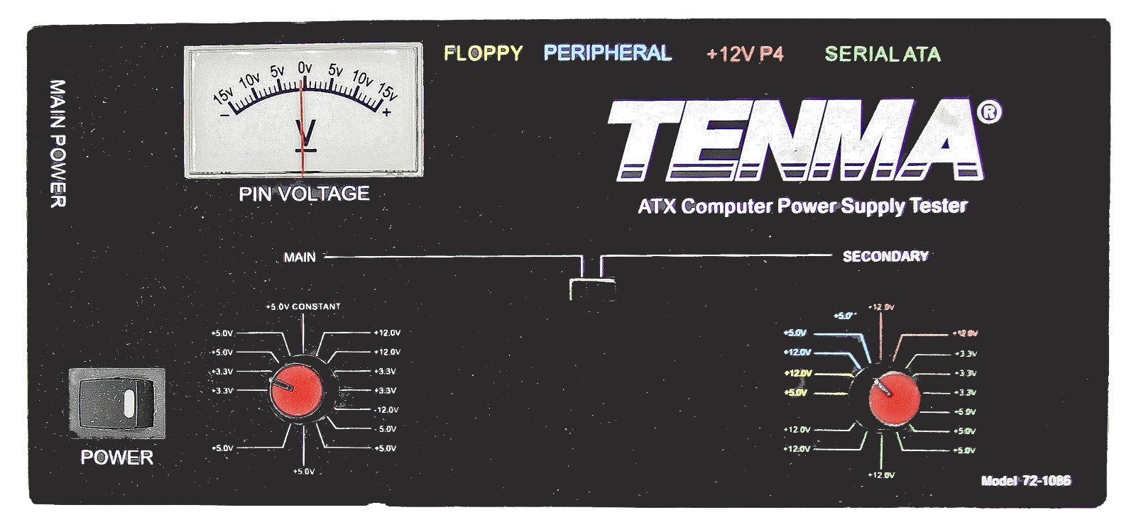
Tenma Model 72-1082 ATX Power Supply Tester:
$36.00
The Tenma Model 72-1082 ATX PowerSupply Tester is designed to provide fast convenient
connector to this tester willprovide immediate visual indication of operation of the power supply.
Typically, ATX style powersupplies are switched on/off from the motherboard. The Tenma ATX
Power Supply Tester simulates thiscommand by placing a proper current load across Pin4 and
Pin5 of the 20-pin ATX connector.When its rocker switch is placed in the ON position, the power
supplies cooling fan will engage,and the LED indicator, located in the tester rocker switch, will
light. This indicates that thepower supply is functioning. In most cases, this level of pass/fail
testing is all that is required.
In some circumstances where thesupply is operational yet erratic behavior exists, it may be
desirable to verify correctvoltage of the +3.3V, +5V, +12V (and –5V where applicable), outputs.
Using a separate voltmeter (notincluded) the voltage of each output may be measured.
• Disconnect the computer powersupply from the AC power source
• Disconnect all IDE and otherdevices that are connected to the computer power supply
• Disconnect the large 20-pin ATXconnector from the motherboard
• Set the rocker switch on thetester to the OFF position
• Connect the 20-pin ATXconnector, from the power supply, to the tester
• Connect the computer powersupply to an AC power source
• Set the rocker switch on thistester to the ON position
• If the LED on the rocker switchlights, the power supply is functioning
Testing Output Voltage
Test pins are located at each ofthe following locations on the 20-Pin ATX connector for voltage
such as the Tenma Model 72-7770(available separately). To measure voltage, place the (–) lead
in connector Pin3. Then place the(+) lead in the pins as shown below to measure each output
Pin Voltage
2 +3.3VDC
3 0V
10 +12.0VDC
18 – 5.0VDC (not used on all ATXstyle supplies)
20 + 5.0VDC
Note:
If an analog meter is used tomeasure the –5VDC on Pin18, the test leads must be reversed.
Place the (–) lead in Pin18, andthe (+) lead in Pin3. In this arrangement, the proper voltage will
measure +5VDC.
Tenma Model 72-1082 ATX Power Supply Tester
$36.00
TENMA PROGRAMMABLE DC POWER SUPPLY-Model 72-8795
$550.00
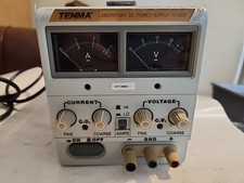
TENMA LABORATORY DC POWER SUPPLY MODEL 72-2005 -
$119.00

Popular Tutorials
Alarms and Indicator Circuit diagrams- Power supply failure alarm
- Theft preventer alarm
- Rain Alarm
- A simple electronic buzzer
- Water Level Indicator with alarm
- Stereo Channel Selector
- Low cost intercom using transistors
- Infrared Head Phones
- Use the CD-ROM drive as a audio CD player without the computer
- Audio Visual Indicator for Telephones
- Ultrasonic pest repellent
- Charge Monitor for 12V lead acid battery.
- Wiper Speed Control
- Dome Light Dimmer for Cars
- Car anti theft wireless alarm.
- Control electrical appliances using PC
- Simple Analog to Digital Converter
- PC based Frequency Meter
- 7 segment rolling display using PC
- Electronic Scoring Game
- JAM(Just A Minute) Circuit
- Flashy Christmas Lights
- TV remote control blocker
- Light Flasher (blinking lights)
- Automatic Dual output Display
- Emergency Light
- Automatic Room Lights
- Running Message Display
- Automatic Speed Controller for fans & Coolers
- Soft Button type Motor Direction Controller
- Super simple stepper motor controller
- Discrete component motor direction controller
- Negative supply from single positive supply
- Self switching Power Supply
- Ultra low drop linear voltage regulator
- Car anti theft wireless alarm.
- Long range FM transmitter
- Remote control using VHF modules
- 40 meter Direct Conversion Receiver
- Remote control using VHF modules
- Remote control using telephone
- A simple Remote control Tester
- Clap Activated Remote
- Radio Remote Control using DTMF
- Ultrasonic switch
- Magnetic proximity sensors
- Dew sensor
- Color Sensor
- Metal Detector
- Optical toggle switch using a single Chip
- Telephone Ringer using 556 dual timers
- Two line intercom plus a telephone changeover switch
- Telephone line based audio muting and light on circuit
- Having secrecy in parallel telephones
- Telephone call meter using calculator & COB
- High Resistance Voltmeter
- A simple Remote control Tester
- Contactless Mains Voltage Indicator
- Zener Diode Tester