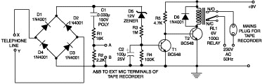
This circuit enables automatic switching-on of the tape recorder when the handset is lifted. The tape recorder gets switched off when the handset is replaced. The signals are suitably attenuated to a level at which they can be recorded using the ?MIC-IN? socket of the tape recorder.
Points X and Y in the circuit are connected to the telephone lines. Resistors R1 and R2 act as a voltage divider. The voltage appearing across R2 is fed to the ?MIC-IN? socket of the tape recorder. The values of R1 and R2 may be changed depending on the input impedance of the tape recorder?s ?MIC-IN? terminals. Capacitor C1 is used for blocking the flow of DC.
The second part of the circuit controls relay RL1, which is used to switch on/off the tape recorder. A voltage of 48 volts appears across the telephone lines in on-hook condition. This voltage drops to about 9 volts when the handset is lifted. Diodes D1 through D4 constitute a bridge rectifier/polarity guard. This ensures that transistor T1 gets voltage of proper polarity, irrespective of the polarity of the telephone lines.
During on-hook condition, the output from the bridge (48V DC) passes through 12V zener D5 and is applied to the base of transistor T1 via the voltage divider comprising resistors R3 and R4. This switches on transistor T1 and its collector is pulled low. This, in turn, causes transistor T2 to cut off and relay RL1 is not energised.
When the telephone handset is lifted, the voltage across points X and Y falls below 12 volts and so zenor diode D5 does not conduct. As a result, base of transistor T1 is pulled to ground potential via resistor R4 and thus is cut off. Thus, base of transistor T2 gets forward biased via resistor R5, which results in the energisation of relay RL1. The tape recorder is switched ?on? and recording begins.
The tape recorder should be kept loaded with a cassette and the record button of the tape recorder should remain pressed to enable it to record the conversation as soon as the handset is lifted. Capacitor C2 ensures that the relay is not switched on-and-off repeatedly when a number is being dialled in pulse dialing mode.
If there are any problems please contact [email protected]