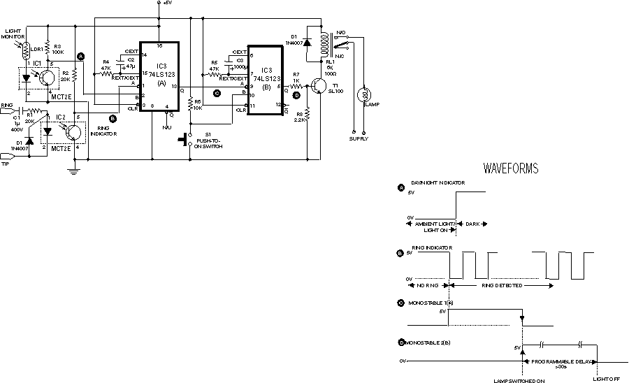
The circuit shown here is used to switch on a lamp when the tele- phone rings, if the ambient light is insufficient. The circuit uses only two ICs and it can be implemented very easily. A light dependent resistance (LDR), with about 5 kilo-ohms resistance in the ambient light and greather than 100 kilo-ohms in darkness, is at the heart of the circuit. The circuit is fully isolated from the phone lines and it draws current only when the phone rings. The circuit provides automatic switching on of a lamp during darkness when the phone is kept in a place such as the bedroom. The lamp can be battery powered to provide light during power failure or load shedding. This avoids delay in attending to a call. The light switches off automatically after a programmable time period and it needs no attention at all. If required, the lamp lighting period can be extended by simply pressing a pushbutton switch (S1). The first part of the circuit functions as a ring detector. When telephone is on-hook, around 48V DC is present across the TIP and RING terminals. The diode in the opto-coupler is ?off? during this condition and it draws practically no current from he telephone lines. The opto-coupler also isolates the circuit from the telephone lines. Transistor in the opto-coupler is normally ?off? and a voltage of +5V is present at the ring indicator line. When telephone rings, an AC voltage of around 70-80V AC, which is present across the telephone lines, is used to turn on the diode inside the opto-coupler (IC2) which in turn switches on transistor inside the opto-coupler. The voltage at its collector passes through 0-volt level during ringing to trigger IC3 74LS123(A) monostable flip-flop. The other opto-coupler (IC1) is used to detect the ambient light condition. When there is sufficient light, LDR has a low resistance of about 5 kilo-ohms and the transistor inside the opto-coupler is in ?on? state. When there is insufficient light available, the resistance of LDR increases to a few mega-ohms and the transistor switches to ?off? state. Thus the DC voltage present at the collector of transistor inside the opto-coupler is normally 0V and it jumps to 5V when there is no light or insufficient light. The 74LS123 retriggerable monostable multivibrator is used to generate a programmable pulse-width. The first monostable 74LS123(A) generates a pulse from the trigger input available during ringing, provided its pin 2 input (marked B) is logic high (i.e. during darkness). It remains high for the programmed duration and switches back to 0V at the end of the pulse period. This high-to-low transition (trailing edge) is used to trigger the second monostable flip-flop 74LS123(B) in the same package. Output of the second monostable is used to control a relay. The lamp being controlled via the N/O contacts of the relay gets switched ?on.? The ?on? period can be extended by simply pressing pushbutton switch S1. If nobody attends the phone, the light turns off automatically after the specific time period equal to the pulse-width of the second flip-flop. The light sensitivity of LDR can be changed by changing resistance R2 connected at collector of the transistor in light monitor circuit. Similarly, switch-on period of the lamp can be controlled by changing capacitor C3?s value in the second 74123(B) monostable circuit
If there are any problems please contact webmaster@electronic-circuits-diagrams.com