During summer nights, the temperature is initially quite high. As time passes, the temperature starts dropping. Also, after a person falls asleep, the metabolic rate of one?s body decreases. Thus, initially the fan/cooler needs to be run at full speed. As time passes, one has to get up again and again to adjust the speed of the fan or the cooler.The device presented here makes the fan run at full speed for a predetermined time. The speed is decreased to medium after some time, and to slow later on. After a period of about eight hours, the fan/cooler is switched off.Fig. 1 shows the circuit diagram of the system. IC1 (555) is used as an astable multivibrator to generate clock pulses. The pulses are fed to decade dividers/counters formed by IC2 and IC3. These ICs act as divide-by-10 and divide-by-9 counters, respectively. The values of capacitor C1 and resistors R1 and R2 are so adjusted that the final output of IC3 goes high after about eight hours.The first two outputs of IC3 (Q0 and Q1) are connected (ORed) via diodes D1 and D2 to the base of transistor T1. Initially output Q0 is high and therefore relay RL1 is energised. It remains energised when Q1 becomes high. The method of connecting the gadget to the fan/cooler is given in Figs 3 and 4.

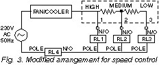
It can be seen that initially the fan shall get AC supply directly, and so it shall run at top speed. When output Q2 becomes high and Q1 becomes low, relay RL1 is turned ?off? and relay RL2 is switched ?on?. The fan gets AC through a resistance and its speed drops to medium. This continues until output Q4 is high. When Q4 goes low and Q5 goes high, relay RL2 is switched ?off? and relay RL3 is activated. The fan now runs at low speed.Throughout the process, pin 11 of the IC is low, so T4 is cut off, thus keeping T5 in saturation and RL4 ?on?. At the end of the cycle, when pin 11 (Q9) becomes high, T4 gets saturated and T5 is cut off. RL4 is switched ?off?, thus switching ?off? the fan/cooler.Using the circuit described above, the fan shall run at high speed for a comparatively lesser time when either of Q0 or Q1 output is high. At medium speed, it will run for a moderate time period when any of three outputs Q2 through Q4 is high, while at low speed, it will run for a much longer time period when any of the four outputs Q5 through Q8 is high.If one wishes, one can make the fan run at the three speeds for an equal amount of time by connecting three decimal decoded outputs of IC3 to each of the transistors T1 to T3. One can also get more than three speeds by using an additional relay, transistor, and associated components, and connecting one or more outputs of IC3 to it.
In the motors used in certain coolers there are separate windings for separate speeds. Such coolers do not use a rheostat type speed regulator. The method of connection of this device to such coolers is given in Fig. 4.
The resistors in Figs 2 and 3 are the tapped resistors, similar to those used in manually controlled fan-speed regulators. Alternatively, wire-wound resistors of suitable wattage and resistance can be used.


If there are any problems please contact webmaster@electronic-circuits-diagrams.com