electronics circuits diagrams,hobbyists zone


Click here for Electronic Circuits main page
 

Factory Siren                                  Click here for Circuit Diagram.

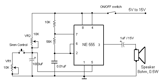
This circuit produces a sound similar to a factory siren.
It makes use of a 555 timer Ic used as an astable multivibrator of a center frequency of about 300Hz.
The frequency is controlled by the pin 5 of the IC. When the supply is switched ON, the capacitor charges slowly and this alters the voltage at pin 5 of the IC hence the frequenct gradually increases.
After the capacitor is fully charged, the frequency no longer increases. Now when the push button siren control switch is held depressed, the capacitor discharges and the siren frequency also decreases.
The presets VR1 and VR2 should be adjusted for optimum performance.


Home | Electronic Circut Design | Tutorials | Newsletters | Discussion Forum | Links | Downloads | Contact


Disclaimer: All the information present on this site are for personal use only. No commercial use is permitted without the prior permission from the authors of this website. All content on this site is provided as is and without any guarantee on any kind, implied or otherwise. We cannot be held responsible for any errors, omissions, or damages arising out of use of information available on this web site. The content in this site may contain COPYRIGHTED information and should not be reproduced in any way without prior permission from the authors.

Copyright © www.electronic-circuits-diagrams.com 2006 - All rights reserved.