Electronics Forum

Electronics Circuits & Projects discussion forum. Get help with electronics.


Garage door type switch...

New to electronics? Don't know where to start. No problem! Post your questions here.

Moderator: pebe

Garage door type switch...

Postby holbrooka » Wed Aug 28, 2013 1:58 am

Hello,
I am trying to make a tv lift, I decided the $600 or so for the ones that are already made are:
1) More expensive than the TV
2) Way more $$ than I have and
3) I have LOTS of time lately, so a project is in order!

My plan: To simply us a drill to run a scissor lift (stab jack) to raise and lower the TV (some additional guides and tracks, too)

I have spent much time beating my head against the keyboard (aka google search), trying to find the right motor, gear head, etc., etc., etc... and decided the drill should work just fine and costs NOTHING as it sits in the bottom of the tool box.

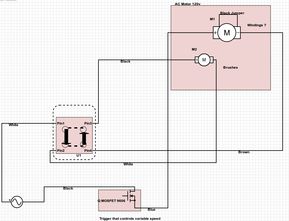
The drill is 120VAC, variable speed with a manual reversing switch, and I have used it manually to raise and lower the TV on the lift (so I know it's got enough to do the job - not sure about long term, but at least it goes!)

What I would like to do is install a set-up similar to the automatic garage doors. With ONE button that make the garage door go UP/STOP/DOWN/STOP/UP/STOP/DOWN, etc... and also two limit switches which have the same effect, when it hits the limit switch it stops and when the button is pushed again it goes in the opposite direction it was traveling before. (I think that makes sense.)

I have looked on the forum and seen similar circuits, each that I found seemed to have an associated timer and I am not sure how to compensate for that. Also, I have an existing garage door opener (motor, circuit board and all) that I can bastardize to make this work, if I knew what to connect to what.

Any direction at all would be appreciated.

Thanks
Adam
Image
holbrooka
 
Posts: 20
Joined: Wed Aug 28, 2013 1:00 am

Re: Garage door type switch...

Postby pebe » Wed Aug 28, 2013 3:06 pm

Provided you can change the motor direction by changing over a 2way switch, then one of the existing circuits here could be modified to suit your need.
pebe
 
Posts: 1058
Joined: Tue Dec 09, 2003 11:12 pm
Location: Ellon, Scotland

Re: Garage door type switch...

Postby holbrooka » Thu Aug 29, 2013 1:57 am

Thank you for the reply! I appreciate it! I'm a little confused as to how I would do what you suggest, but before I ask any more questions, I am working on posting the schematic in detail for the drill (I had it finished on Schemeit, but didn't know I had to register in order to save it and when it took me through the registration process, the schematic is nowhere to be found! Drat! But I'll get it done here tomorrow)

I'm already a little concerned because the drill motor has brushes while the larger garage door opener does not have any brushes... I'll get a schematic out and see if y'all think it will work or if I should start from scratch.

Thanks again! You'll be hearing from me soon!
Adam
holbrooka
 
Posts: 20
Joined: Wed Aug 28, 2013 1:00 am

Re: Garage door type switch...

Postby holbrooka » Thu Aug 29, 2013 5:48 pm

Okay, here is the drill schematic (if I am using that term correctly?)

I have a few issues I am not sure how to deal with 1) the garage door opener has an RPM sensor (the reluctor) that I will need to bypass. It seems to generate between .5 and .9 volts ac(with my volt meter I get zero with it set on DC and .7-.9 with it set on ac - seems a bit off to me?) I'm not sure if that is possible.

2) I am not sure how to wire for the brushes from the garage door board, yet! I'm still working on that one!

So two questions today if anybody is interested. 1) any way to bypass the RPM sensor (that would be easier than starting from scratch)
and 2) Should I just start from scratch? Would it be easier?

Thanks y'all!
Adam

also, for the drawing, the "switch" with pins 1-4 is a manual switch it connects pin 1 to 3 or 1 to 2, while at the same time connecting pin 4 to 2 or 4 to 3 (not sure if my attempt at putting that down was accurate. (is there a "part" for this I missed, couldn't find it in switches (that I know!))
Image
holbrooka
 
Posts: 20
Joined: Wed Aug 28, 2013 1:00 am

Re: Garage door type switch...

Postby pebe » Thu Aug 29, 2013 7:11 pm

Part of the circuit is missing, as with your earlier wiring diagram. Could you reduce its size to fit the screen?
pebe
 
Posts: 1058
Joined: Tue Dec 09, 2003 11:12 pm
Location: Ellon, Scotland

Re: Garage door type switch...

Postby holbrooka » Thu Aug 29, 2013 9:18 pm

Sorry about the image size. I didn't realize they showed up differently. In the preview they show up completely on my desktop. On my laptop I see that part is missing. I right clicked on it and chose "open in a new window" and it shows the complete image. Hope that helps - if not I can convert it to a lower resolution and see if that drops the size.

Newest updates for the project...

I have the drive shaft assembled and have tested it out with my 18v drill, and it works nicely, a bit of a strain at some parts so I am going to put in pulley lift (like double hung windows) to give the motor a break.

ALSO... I was able to attach the RPM (reluctor) to the drive shaft so I should be able to use it as is (so long as it is okay with the rpms, which might be kind of slow for it :/

On the schematics, I did not know how to make a motor with brushes and coils with all that attachments so the diagram may be a stretch to understand. Again, if you steer me in the right direction on how to fix that, I'll make it look purty!

Thanks!

Adam (and let me know if the image thing works for you or not.)
holbrooka
 
Posts: 20
Joined: Wed Aug 28, 2013 1:00 am

Re: Garage door type switch...

Postby pebe » Thu Aug 29, 2013 10:28 pm

Yes. Got it alright with right click - but still had to scroll up/down.

If you want to use that motor I can draw up a circuit for you.
pebe
 
Posts: 1058
Joined: Tue Dec 09, 2003 11:12 pm
Location: Ellon, Scotland

Re: Garage door type switch...

Postby holbrooka » Fri Aug 30, 2013 2:47 am

Wow! That would be awesome!!!

Please let me know if you need more detail on the motor or anything. Also, what I can do to help. (I know, sometimes help from noob's is more work, but I love to learn so I will offer :)

Adam
holbrooka
 
Posts: 20
Joined: Wed Aug 28, 2013 1:00 am

Re: Garage door type switch...

Postby pebe » Fri Aug 30, 2013 1:49 pm

I think I got the details of your motor OK. Here is the circuit and it’s about as simple as you can get. It uses a relay to reverse the polarity of the armature (the winding with brushes) relative to the field coil (fixed winding) of the motor. You will need a 12V supply.

First, the relay driver. A 555 is used in its bistable mode like this: Pin2 is connected to pin6. When pin2 is taken below 1/3 of Vs (the supply voltage) the output pin3 goes high, turning on the double pole changeover relay. When pin6 is taken to above 2/3 of Vs the output goes low turning off the relay. When pins2 & 6 are taken to ½ of Vs (R1=R2) there will be no change of output and it will remain in its previously commanded state. Pins5 and 7 are left unconnected.

Now how the 555 toggles. Assume Vs = 12V. When the 555 is first switched on, C1 is discharged so as Vs rises, pin6 is taken to Vs and pin3 goes low. Then C1 charges up via R2 so the voltage on pins2 & 6 is 6V. C2 is discharged so the voltage at B1 = 0V. When the push button is operated, C2 pulls down pin2 to 0v and sets the bistable, taking pin3 high. Now C2 charges up via R3 until the voltage at B1 reaches the pin3 voltage (about 10.5V). When the pushbutton is again pressed, B1 voltage is impressed on pin6 and the 555 resets (pin3 low). C2 discharges via R3 to 0V and that’s where we came in!

Now for the relay and motor. The diode across the relay coil is the usual one to prevent spikes from the relay as it turns off. L1 is the bottom limit switch and L2 is the top one. Both are normally closed switches and go open when the motor gets to the end of its travel.

The contacts as shown are when the lift is lowered and at rest. L1 is the bottom limit switch. While the lift was going down L1 would have been closed and current would have flowed through Sw 1to 3, through the armature, through L1, Sw 5 to 4, then the field winding. When the lift hits the bottom, L1 will open cutting off the motor.

When the button is pushed again the relay turns on. Sw 1 makes with 2 and Sw 4 makes with 6. Current now flows through the armature winding in the reverse direction (making the motor go in reverse) and L2. The lift rises until it hits the top limit and L2 opens, stopping the motor. Meanwhile, as the lift rises off the bottom stop, L1 would have closed ready for the return trip. The next button press will turn off the motor and the lift will go down again. Note that if you press the button at any time when the lift is moving, the motor will change direction.

When you construct it, make sure you keep the 120V supply well away from the 12V one. When you are ready to go, set the lift halfway so that you can check the motor direction is right. If it isn’t, reverse the field winding connections.

I hope that’s clear, but if you have any queries, just shout.
Attachments
555 flip flop.GIF
555 flip flop.GIF (5 KiB) Viewed 47015 times
pebe
 
Posts: 1058
Joined: Tue Dec 09, 2003 11:12 pm
Location: Ellon, Scotland

Re: Garage door type switch...

Postby holbrooka » Tue Sep 03, 2013 8:20 pm

WOW!!! That is awesome!!!

It was Labor Day Weekend here in the states and I was out camping. Just got back home last night at almost midnight. I've been chomping at the bit to check this out!!!

Thank you VERY much for your schematic!!!

I'll have a chance tomorrow to take a look at it and see if I understand it all and what questions I might have!!

Thanks again, this is great!

Adam
holbrooka
 
Posts: 20
Joined: Wed Aug 28, 2013 1:00 am

Re: Garage door type switch...

Postby holbrooka » Wed Sep 11, 2013 8:26 pm

Okay, so it has taken me much more time to get to this than I had hoped! I have spent today figuring out parts and here is what I have in my shopping cart:


4.7nF/50V Radial Ceramic Disc Capacitor DE1428 1971 $0.09 $0.45
100nF/50V Radial Ceramic Disc Capacitor DE1444 10391 $0.12 $0.60
10k Ohm 0.5W Carbon Film Resistor ±5% 103 DE2954 1852 $0.12 $0.61
220k Ohm 0.5W Carbon Film Resistor ±5% M22 224 DE2970 682 $0.12 $0.61
NE555P General Purpose Bipolar Timer 555 NE555 DE1733 1804 $0.25 $1.25
Small Signal Diode 100V/200mA Fairchild or NXP 1N4148 E3230 2539 $0.12 $0.60
Subminiature DIP DPDT Relay 12V - 2A@250VAC AZ822-2C-12DSE DE2721 20 $2.35 $4.70
MOSFET Transistor N-Channel 150V/43A IRF3415 DE3564 45 $2.61 $2.61

SPDT Snap-Action Standard Micro Switch with Roller Lever $1.35 $2.70
(Standard micro switch. Specifications: • Current rating: 10A @ 125 VAC and 250 VAC • Housing dimensions: 28.8 mm L x 15.8 mm W x 10.3 mm D • Contacts: 3 • Approval: UL.)
Image

I wasn't so sure about the specs on the 555, the relay and the switches, but I think they will work.

You might also notice that I have a MOSFET thrown in there.... this is for another question I have. Currently the drill has a MOSFET connected to the triger that controls the voltage. I'd like to be able to control the voltage and adjust it easier than sinking a hot paperclip through the trigger to keep it where it needs to be. So I was hoping to incorporate a MOSFET and some sort of dial adjuster (a potentiometer?), but so far I have not found anything that is that simple. I guess I am missing something, but so far I can't figure it out. (I'm guessing this would work as the drill is a 120volt, 3.5 amp drill 0-1300 rpm)

Also, regarding the 12v power supply, does this need to be ac or dc or does it matter. Finally, I have a remote control (from the garage door which operates on 24v ac, which I would LOVE to incorporate into this schematic. Is there any way I can make this a 24v ac system so I can just plug it into the system?

Okay, thank you again for all your help!!!

I am getting really excited to get this going. I have been playing with the garage door circuits as well, to see if I can get it working. So far I have been able to get one orange lead to fire up, but only with a continual button push (as the rpm sensor is not happy about not having any current through it!) Speaking of, how would I set up a current of .7v ac to flow through it from the 120v ac that comes in? I saw that someone used an invertor oscillator and a piezo buzzer to do this, but I don't think having an extra noise in the tv cabinet would work out that well! - this is actually not that important if I can get the other circuit working... just more of interest in how things work to me!

Thanks again!!!

Adam
holbrooka
 
Posts: 20
Joined: Wed Aug 28, 2013 1:00 am

Re: Garage door type switch...

Postby pebe » Fri Sep 13, 2013 2:22 pm

holbrooka wrote:Okay, so it has taken me much more time to get to this than I had hoped! I have spent today figuring out parts and here is what I have in my shopping cart:.................
.........I wasn't so sure about the specs on the 555, the relay and the switches, but I think they will work.

No problem with any of them. 1/4W resistors would have been adequate, but no problem with 1/2W ones.

I am not sure why you want a MOSFET. If your drill is for use on 12VAC it will almost certainly use a Triac, not a MOSFET.
The speed regulator will use a capacitor charged through a variable resistor. If you dismantle the drill you will be able to see the variable resistor attached to the trigger. You can measure its resistance with an ohmmeter and replace it with an external rotary potentiometer (or 'pot'). TAKE CARE! 120V can kill! Ensure you insulate the terminals and ground the case of the pot.
Also, regarding the 12v power supply, does this need to be ac or dc or does it matter.

The supply needs to be DC, with the positive terminal connected at the '+12V' I have shown at the top of the circuit.
Finally, I have a remote control (from the garage door which operates on 24v ac, which I would LOVE to incorporate into this schematic. Is there any way I can make this a 24v ac system so I can just plug it into the system?

I cannot answer that question without knowing a lot more about your 24VAC system
pebe
 
Posts: 1058
Joined: Tue Dec 09, 2003 11:12 pm
Location: Ellon, Scotland

Re: Garage door type switch...

Postby holbrooka » Fri Sep 13, 2013 3:28 pm

You are awesome!!! Okay, I'd like to focus on just getting this thing running. I'll deal with the remote control aspect later, if I get to it!

Sorry for my ignorance! I had already taken the trigger assembly apart and with my limited understanding of electronics deduced it to be a MOSFET that I was looking at (after the usual web searching).

I believe you are right, it looks like a Triac (but I've enclosed a picture of the little circuit board and trigger assembly as I have proven myself unreliable!)
ImageImage

Regardless, it sounds like I can use a potentiometer to adjust the motor speed! That is AWESOME ... but that brings up the next question... how do I incorporate that into the circuit? (Or perhaps there is a better way than using a potentiometer, and I have just steered you in that direction by my ignorance?)

Thank you for all your help!!! I feel like there is light at the end of the tunnel!!!

Adam
holbrooka
 
Posts: 20
Joined: Wed Aug 28, 2013 1:00 am

Re: Garage door type switch...

Postby holbrooka » Fri Sep 13, 2013 4:07 pm

In my searches I came up with this little circuit. Looks like it is a kit that comes for me to assemble, the specs look right (to my untrained eye).
Image
Specs:
FK415: LIGHT DIMMER 500W
• Using TRIAC semiconductor for reliable dimming.
• Max. load: 500 W.
• Power supply: 220VAC.
• PCB dimensions: 1.01 X 1.46 in.
• Recommended housing: Future Box (FB14)

Is this a reasonable option for controlling the motor speed? (I am assuming it would go on the black lead from the 120 from your diagram. And I am not so sure why there are two pins for "IN" and two pins for "OUT"

Trying to help myself out, but, again, I may be doing more misleading than help. Let me know.

Thanks again!

Adam
holbrooka
 
Posts: 20
Joined: Wed Aug 28, 2013 1:00 am

Re: Garage door type switch...

Postby pebe » Fri Sep 13, 2013 6:14 pm

Yes, that dimmer would do the trick. Why 4 terminals? Well, remember the intention was probably be assemble the unit in a box and connect it in series between the 120V supply lead and the drill or other device, so it's only necessary to cut the lead and connect the 120V to the 'input' terminals and the load to the 'output'. You can use it that way and short out the two leads going to the trigger control to make it ineffective.

Note that only 2 pins are actually needed in the dimmer - the triac input and output. The other two are merely a link for the neutral wire, so you can see it functions the same as your exiting trigger circuit.
pebe
 
Posts: 1058
Joined: Tue Dec 09, 2003 11:12 pm
Location: Ellon, Scotland

Next

Return to Electronics newbies


Who is online

Users browsing this forum: No registered users and 7 guests


cron