Electronics Forum

Electronics Circuits & Projects discussion forum. Get help with electronics.


high amperage regulated power supply help

Discuss about electronic circuits here. Request help for circuits that you couldn't find anywhere else, how a circuit works etc. Discuss anything related to electronic circuits.

Moderator: pebe

high amperage regulated power supply help

Postby maddios » Thu Aug 11, 2011 4:48 pm

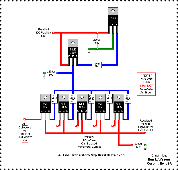
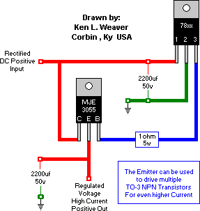
Hi guys, I'm trying to build a high power regulated power supply for a 12v fan (need about 30A at 12V) control and I found a website where such a power supply is discussed.

In these pictures a power supply is laid out:
Image
Image

However, I'm not really getting how the voltage regulator is capable of controlling the output voltage without any kind of loop back.

Also, when I put it together I'm getting a .3v drop between each of the stages of transistors, is this normal? eg from vr I get 8.97v, but after the first mje3055 I get 8.69v, and after the 2nd set of amplification I get 8.3v. Is that normal?


Thanks guys, I'm a total beginner when it comes to circuits but I'm trying to learn as this stuff is really interesting.
maddios
 
Posts: 2
Joined: Thu Aug 11, 2011 4:42 pm

Postby awright » Tue Aug 23, 2011 7:42 am

Yes, these voltage drops are completely normal and, in fact, lower than I would expect.

This circuit is very simplistic, consisting merely of two cascaded emitter follower stages, one with a single MJE3055 and a second with five MJE3055s. There is no overall feedback to tightly control the output voltage which will vary with load current (and temperature).

For driving a fan, the absence of feedback probably does not matter. There will be some uncompensated dependence of output voltage on load current, but does that matter for your application? (By the way, what kind of fan draws 30 amps at 12 volts DC and why does the voltage have to be regulated?)

Part of the voltage drop you are seeing is due the the Vbe (Voltage base-to-emitter) that you will find in the MJE3055 data sheet. The data sheet (http://alumni.cs.ucr.edu/~sneema/mje3055t.pdf) says, "[VBE (on) *Base-Emitter On Voltage @ VCE = 4V, IC = 4A is 1.8 V]." This means that the voltage drop from base to emitter is 1.8 volts with an emitter current of 4 amps and with a voltage of 4 volts from collector to emitter. They note that this is tested with pulses of 300 msec duration in a pulse train of 2% duty cycle. Testing this way minimizes transistor heating during the test.

Since you are observing only about 0.3 volts from base to emitter, I presume that you are not testing at 30 amps into the load. Vbe is somewhat dependent upon emitter current, but not in a direct ohmic manner.

Another part of the voltage drop you are seeing is due to the ohmic voltage drop in the 1 ohm resistors in series with each MJE3055 base. This can be roughly calculated by assuming a typical value for the current gain of the MJE3055. The spec sheet gives a range of current gains from 20 to 100 at 4 amps and a minimum of 5 at 10 amps emitter current. If you are drawing 30 amps from 5 transistors, that's roughly 6 amps for each transistor, assuming equal sharing of the load current which assumes well-matched MJE3055s. Figure 1 of the spec sheet shows a typical current gain of 30 at 6 amps. That means your base current is roughly 6/30 = 0.2 amps for each output MJE3055. 0.2 amps through 1 ohm = 0.2 volts drop across each base resistor. That will show up as a 0.2 volt drop in the output voltage in addition to the Vbe drop. You can perform a similar calculation for the single MJE3055 driving the 5 bases.

All in all, not a very sophisticated circuit, but simple and possibly ok for driving a fan. Output voltage control is very unsophisticated. The 78xx puts out a nominal voltage of xx volts. The single driver MJE3055 emitter voltage will be xx volts minus (Vbe + the driver stage base resistor drop). The emitter voltage of the five output MJE3055s will be the emitter voltage of the driver stage minus (Vbe + the average output stage base resistor voltage drop).

To obtain reasonably equal sharing of load current between output transistors they should all be from the same production lot so their characteristics are well matched. Poor matching of output transistors could result in poor load sharing and possible sequential burnout of all output transistors.

You can compensate for the cumulative voltage drop by substituting an adjustable three-terminal voltage regulator for the 78xx or by inserting a few forward-biased small-signal diodes between the "ground" terminal of the 78xx and circuit ground.

awright
awright
 
Posts: 11
Joined: Wed Jan 28, 2004 7:59 am
Location: Oakland, CA

Postby maddios » Tue Aug 23, 2011 8:55 pm

Thanks for the thorough explanation awright, I had a feeling that's what was going on simply from logically looking at the connections in the diagram.

The 30amp motor is an auxiliary cooling fan on the front of my car's radiator. It's not really 30A, it's actually about 12-13A, but it has a very large in-rush current of over 30A when it's kicked in at full 14V (car's running voltage), I haven't actually measured these numbers, but just calculated using ohm's law, and the in-rush current calculation simply based upon the fact that it blows a 30A fuse, just barely.

I'm going to alleviate this issue by using an adjustable Voltage regulator, and adjust its voltage from a small PIC to ramp up the output voltage when it's first powered up.

I'm currently working on sourcing a pair of heatsinks for my TO-3 3053, as my proof of concept is mostly working with to-220 (i think) frame 3053s.
maddios
 
Posts: 2
Joined: Thu Aug 11, 2011 4:42 pm

Postby awright » Tue Aug 23, 2011 9:54 pm

There may be a much easier and cheaper, and higher performance way to minimize the inrush current to your radiator fan. I have not applied them, but there are NTC (Negative Temperature Coefficient) power thermistors that have relatively high cold resistance that rapidly decreases to a very low value at rated operating current.

You'd have to look at the specs for the properly rated device, but I believe the voltage drop of the thermistor inrush current limiter at steady-state would be much lower than with your example circuit, preserving for the most part the fan performance that the engineers selected. The device is a simple two-terminal device looking like an MOV surge suppressor, but with totally different characteristics. Probably cost a few dollars, though I've never bought one.

Hope this doesn't deprive you of an excuse to engage in a fancy project design.

awright
awright
 
Posts: 11
Joined: Wed Jan 28, 2004 7:59 am
Location: Oakland, CA


Return to Electronic Circuits Help


Who is online

Users browsing this forum: No registered users and 1 guest


cron