I thought some time ago to make a tutorial on how to use a run-of-the-mill el cheapo digital multimeter.
This tute was supposed to be finished some time ago, but due to illness, I was unable to complete it fully. Sorry about that, but I'll add more to it as I get better.
In the sections I've already finished I will show you how to read resistor values, do continuity, resistor and diode tests. When my health permits, I'll put up transistor testing, how to take voltage readings and what to look out for, as well I will just lightly touch on current measurements, though its an extremely rare fault finding process these days and is rarely required, so I won't spend much time on this topic.
The el cheapo meter in I mentioned above is one I purchased from Jaycar Electronics here in Australia as a backup for my main meter. Here's the link:
Jaycar Multimeter
Unfortunately Jaycar must have recently stocked this newer model which is a little different to the one I purchased from them some time ago. But function selection is identical, as I will explain each one.
I selected this type of meter, not only because its cheap, but it has an auto-ranging facility. Makes life so much easier with this feature.
Accuracy of the meter won't be fantastic, but for everyday normal use, its more than adequate.
The above isn't a plug for Jaycar, as you may find another supplier with a similar product at around the same price or cheaper, but obtaining one with an "Auto-ranging" feature will make life for you using it so much more pleasurable.
If you're into electronics as a hobby, professional or just curious, then a multimeter will go a long way into helping you build and fault find circuits.
When I was plying my trade in TV, video, audio and computer monitor repairs, my multimeter found 95% of the faults. Though a reasonable knowledge of how electronic components work did help somewhat. But the good ol' meter always did the trick.
A word of warning at this point: I would advise you NOT to measure mains AC voltages unless you know 100% what you're doing. Measuring low AC voltages from transformer secondaries, as an example, is fine, but not the power outlet in your home.
AC mains can kill and it can deliver enough current to drop an elephant. The current it can supply is only limited by the mains fuses or breakers, which is around 16 Amps in many domestic homes around the world. It may be lower for 120V AC mains countries though.
Another danger is switch-mode power supplies. Nearly all mains appliances use this form of power transformation. They are much more efficient and cost saving to their transformer counterparts and have been adopted for nearly anything that has to convert AC mains to DC.
They have what they call a HOT an COLD side to them. One side of the switching transformer, (also known as a 'Chopper Transformer') associated with mains is considered the HOT side. Therefore there is no isolation between you and the mains potential, which can float as high as 385 volts DC in a 240V AC country.
The other side of the transformer deals with DC filtering and voltage regulation, and is considered relatively safe. Its actually this transformer that isolates you from the mains.
See Figure 1 for an example schematic and Figures 2 and 3 pictures of a switch-mode power supply showing the component and solder sides.

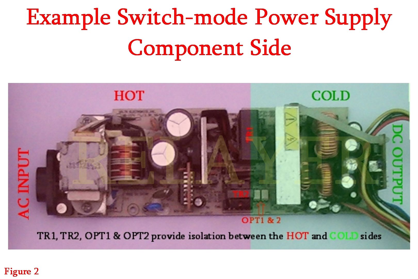

Once again, DON'T touch a switch-mode power supply unless you know fully on what you're doing.
Another forbidden appliance is microwave ovens.
These appliances can be lethal even turned off and unplugged from the mains for up to several weeks.
This is due to a capacitor used in them for tuning the microwaves at the correct frequency and for blocking DC.
They can store a charge for ages due to the high value bleed resistors built into them. If this resistor was to go open circuit, then the capacitor could virtually hold its charge for months.
Microwave ovens usually run at around 5k+ volts and more than 4 Amps, so these values shouldn't be scoffed at.
I've heard of a couple of technicians being killed fault finding a microwaves with it running.
Your body in most cases can feel a reasonable tingle at around 30 volts. But depending upon your body resistance, (it varies for different people), will also determine how much current your body will conduct.
Anything with a high enough voltage and current capability can be lethal, regardless of body resistance.
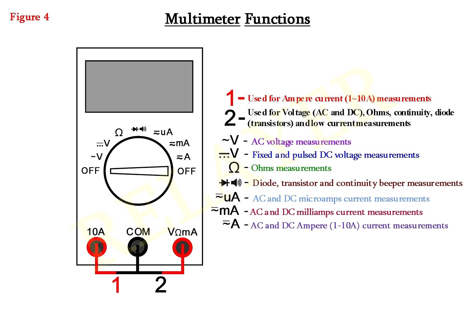
OK, now with the warnings over, lets look at our multimeter.
Figure 4 just shows the meter in its off position, and its various functions.
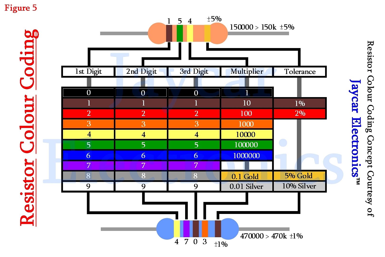
Before we go any further ahead, we need to look at resistor colour codes. Check out Figure 7. (Resistor colour-code concept courtesy of Jaycar Electronics Australia ™)
There are two types of coding system in place that I know of (other than the actual value printed on the resistor), for determining resistor values.
The 1st and easiest is the EIA (Electronic Industries Alliance) and the other is IEC (International Electrotechnical Commission).
EIA use a four band colour coding system, while IEC use five bands.
Low current inductors (that look very similar to resistors), are colour coded as well, but we won't be covering that topic in this tutorial. Quite a few inductors that I know of, have a light green body colouring, though there are exceptions.
Low current inductors are mainly used for RF (Radio Frequency) applications.
In the old days, capacitors were also colour coded, but they are extremely rare to find today, as their values are printed directly to the component now-a-days.
Surface-mount resistors have their values in a mixture of numbers, but are very easy to calculate. Here's an example:
An SMD resistor has a coding as follows: 474
The value is 47 followed by 4 zeros. Therefore its value is 470,000 ohms or 470kΩ. Nice an easy.
Surface mount resistors of the 0604 types and smaller, have no identifying marks on them, as it would be quite difficult to print so small, let alone you being able to read it anyway.
Resistors normally have values between 0Ω and 10MΩ.
EIA types usually have a tolerance of 5% and are made of carbon or cermet. Their values are usually categorized: 1.0, 1.2, 1.5, 1.8, 2.2, 2.7, 3.3, 3.9, 4.7, 5.6, 6.8 and 8.2 and their multiples. i.e. 100, 120, 150 etc.
IEC types are usually 1% tolerance and are made of Metal-Film and have values categorized are: 10, 11, 12, 13, 15, 16, 18, 20, 22, 24, 27, 30, 33, 36, 39, 43, 47, 51, 56, 62, 68, 75, 82, and 91, and their multiples.
Resistors also come in very small values, such as: 0.1, 0.12, 0.15 etc
Wattage ratings can also vary as well, from milli to several hundred watts.
For reading EIA type resistors, the first three bands are the important ones.
Lets say you have the following colours on the resistor:
Band 1: Green, Band 2: Blue, Band 3: Yellow and Band 4: Silver, which is our tolerance.
Green = 5, Blue = 6 and Yellow = 4. Therefore the value will be 56 followed by 4 zeros, which will be 560,000 or 560kΩ. Our tolerance will be 10%.
You might ask, 10% of what? It means the actual measured value could be 10% above or below the colour-coded value. Therefore the 560kΩ resistor could read on your meter between, 565,600 and 554,400 ohms.
Lets do another example:
Band 1: Yellow, Band 2: Violet, Band 3: Gold and Band 4: Gold, is our tolerance.
Yellow = 4, Violet = 7 and Gold = 0.1, and the tolerance is 5%.
Therefore, the value will be 47 followed by 0.1, which means you move one decimal place to the left. Thus the value will be 4.7 ohms.
Our actual measured value could be between 5.17 and 4.23 ohms.
OK, lets touch on the IEC resistors now.
The first four bands are the important ones.
Lets do an example:
Band 1: Red, Band 2: Violet, Band 3: Black, Band 4: Red and Band 5: Brown, which once again is our tolerance.
Red = 2, Violet = 7, Black = 0, Red = 2 and our tolerance will be 1%.
Therefore the value will be: 270 followed by 2 zeros, which will be 27,000 or 27kΩ.
One problem I have with these types of resistors is trying to distinguish Brown and Red. Therefore if I'm making a circuit, I'll measure them with my multimeter prior to installing them just to be certain.
If I have to measure a suspect one in a circuit, I'll lift one leg and measure it, at the same time trying to evaluate the colour coding. If it measures something very close to what I suspect is its value, than all is good. Otherwise I will have to reef it out and look at it under a magnifying glass.
They can be real pains at times.
Lets look at Figure 6. The dial on the multimeter has now been shifted to the ohms range.
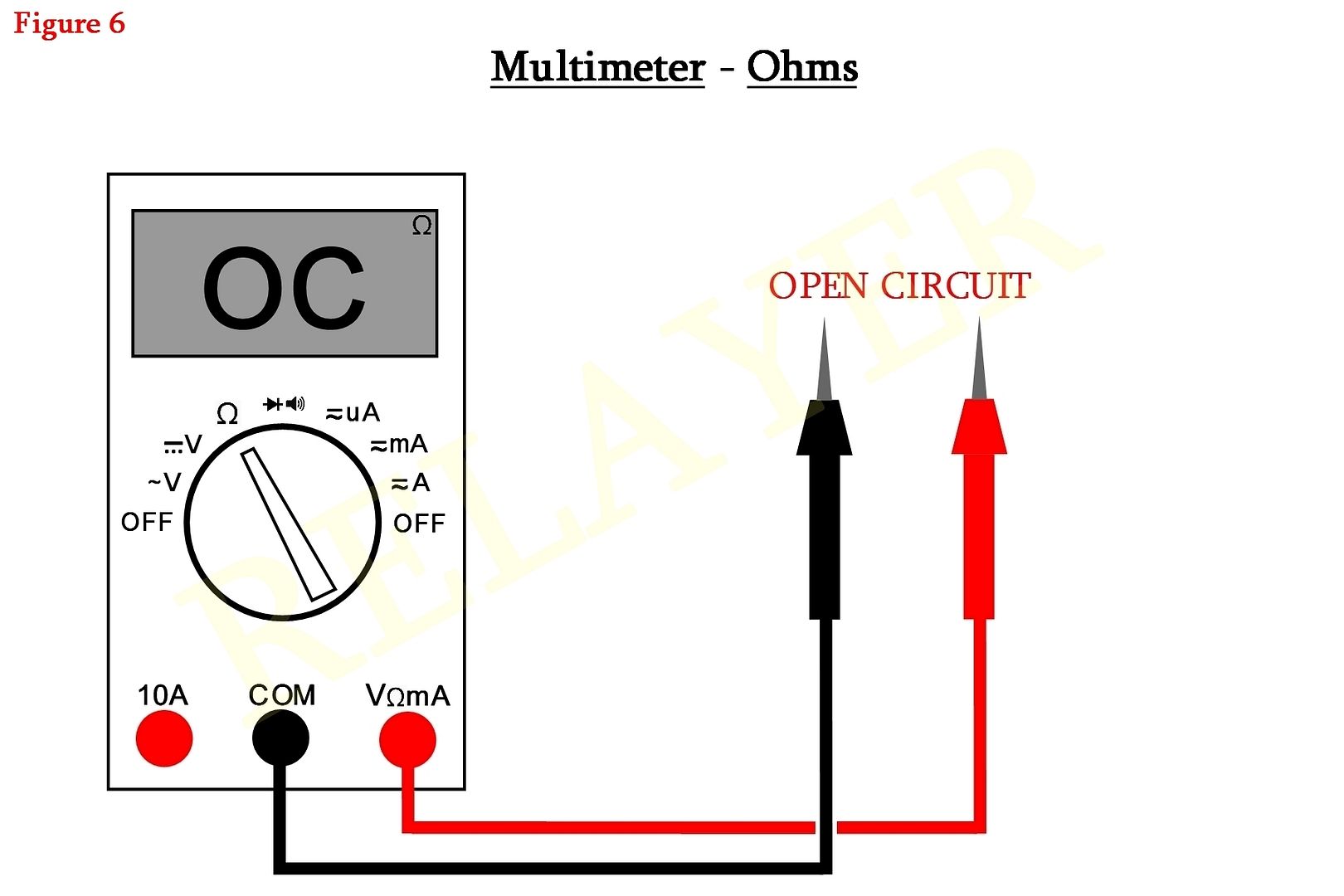
This is showing an open circuit condition and your meter reading will reflect that due to the meter probes not touching each other.
So if you're measuring a resistor, as an example, and its showing the same reading, good chance its open circuit. BUT, to be 100% sure, and if the component is soldered in circuit, then you need to lift one leg, by unsoldering it, then measure it. If it gives the same open circuit reading, then you'll know its 99.9% cactus.
By the way, the most accurate way of testing any component is to lift one leg out of circuit, or remove it entirely, then test it.
In circuit tests are fine if the readings are what you might expect, but due to other components in circuit, they can easily affect your measurements.
Also, on rare occasions a component will measure good, even with other rigorous tests placed on it, replacing it may be the only cure. Electronic components can be very quirky and unpredictable at times, I guess its par for the course for anything these days.
One other note in regards to resistors in a fault condition, is that they go high in their indicated value or go open circuit. In all my years of electronic repairs, I've never come across one that was short circuit.
Next we're going to look at a short circuit condition.
See Figure 7.
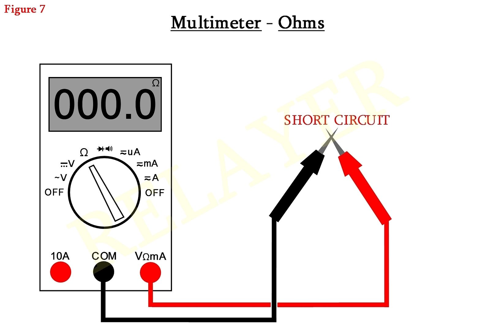
You'll notice that the meter probes have been shorted together and the reading is showing 000.0. Not all meters will give you an absolute zero reading, some may display several hundred milli-ohms or even a couple of ohms: 000.8Ω or 002.5Ω, as examples. Some meters require them to stabilize for several seconds before they will read zero.
This is due to tolerances within the meter itself and even the resistance of your probe wires can affect the readings. This is not critical, the main factor is that it reads close to zero, indicating a short circuit.
Now we will look at measuring a resistor. See Figure 8.
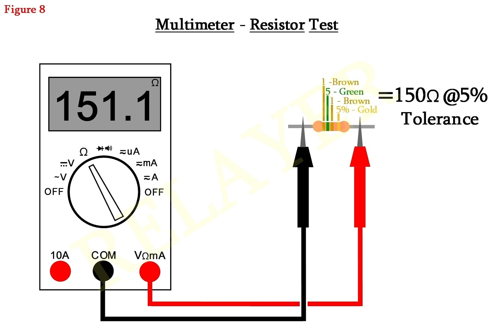
As you can see, going by the colour coding that's indicated on the resistor, we're getting a fairly close reading on the meter. In rare cases you will ever get an exact reading. But going by the last band tolerance, the reading should be within the percentage of the tolerance.
OK, that's all we'll cover regarding resistors.
Next we change the meter dial to our diode and continuity beeper function. Refer to Figure 9.
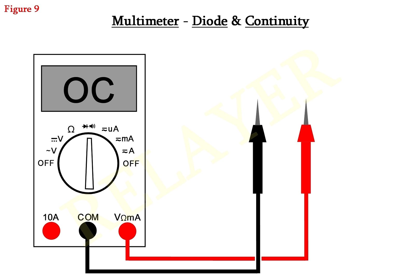
Notice we're in an open circuit codition.
We're now going to short the probes together. There now should be an audible beeping coming from the meter. See Figure 10.
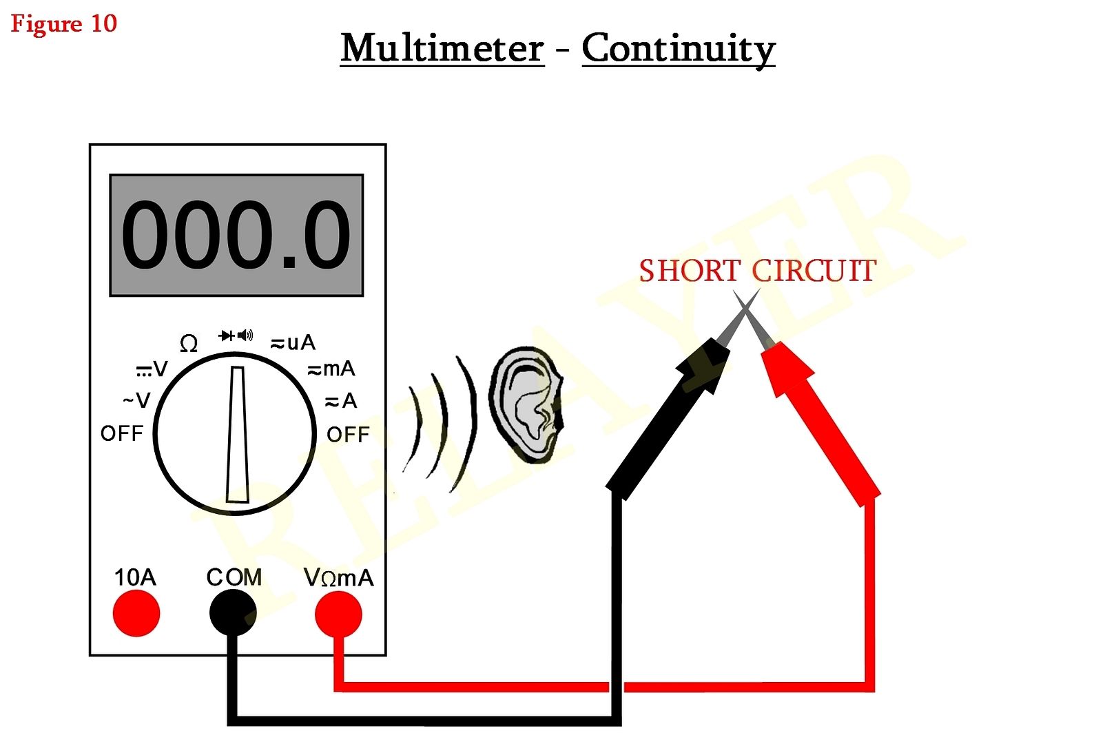
This is an excellent way to check for short circuits or conductor continuity without having to view the meter readings.
You can check wire continuity to make sure there are no breaks somewhere under the wires insulation. Something that you can't see, unless you have x-ray vision or you remove the insulation entirely to look for the break, which wouldn't be practical of course.
Its also great to use this feature if you need to make sure circuit tracks are sound and haven't got any hard to see cracks or track defects.
Depending upon the meter make and model, continuity will be audible up to 100 to 200 ohms. If you get no beeping when checking something that should read a short or virtual short, then switch back to your ohms range and check the resistance. Good chance you have a fault.
Next we are going to look at testing diodes. See Figure 11.
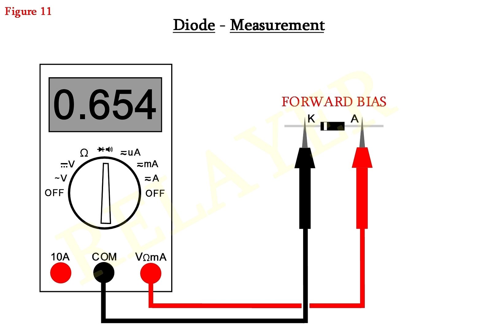
Here we're doing a 'forward bias' test a diode.
Forward bias is a condition whereby the component is conducting in the way its intended to. Though zener diodes are one exception, but I'll get to those further down the page.
i.e. We are making it conduct via a voltage generated by the multimeter itself.
This voltage is around 700 millivolts to 1 volt, though some meters may differ.
It would be nice to explain how diodes and other semiconductors work, but its beyond the scope of this tutorial and it would take pages upon pages to illustrate their workings. Perhaps another tutorial later on I may do this.
Depending upon the diode type, will also depend on its reading. Some diodes, for example, the schottky type, may read as low as less than 100 millivolts, others as high as 1.2 volts and beyond.
The voltage readings you do obtain from forward bias measurements usually indicate the voltage needed to get the component to conduct.
You'll also notice the negative (Black) probe is contacting the cathode (K) side of the diode, and the positive (Red) probe is contacting the anode (A). This is the forward bias condition needed to give us our reading.
Now have a look at Figure 12.

You can now observe that the diode itself has been reversed. Red to cathode (K) and black to anode (A). This is now in the 'reverse bias' condition. You should not get any reading from your meter, it should be an 'open circuit' condition.
If you do get a reading, this will usually indicate that the diode is leaky, therefore unserviceable and should be discarded.
Ideal diodes should not be able to conduct current in the reverse direction. But in an imperfect world, this isn't so. ALL diodes will have some degree of reverse leakage, though in the nano to micro-amp range, to which the meter isn't made sensitive enough to read these small currents. If it were that sensitive, you'd be throwing out all your diodes.
In around say 98% of diodes such low leakage is acceptable for most circuit applications. Though once again, zener diodes are an exception.
Zener diodes are designed to be placed in circuit in the 'reverse bias' condition.
They are designed to regulate a voltage depending upon the value of the zener.
Some typical voltages for them are:
2.7V, 3.0V, 3.3V, 3,6V, 3.9V, 4.3V, 4.7V, 5.1V etc, and right up to hundreds, even thousands of volts.
You would measure zener diodes normally, just like ordinary diodes, though your 'forward bias' readings will usually be much higher. Say from around 700mV and higher.
Doing a 'revers bias' measurement will be the same, but there will be exceptions.
Zener values from 2.7V to 4.7V or a tad higher depending upon your meter, will show some reverse leakage, but this is normal and its due to the amount of current your meter is trying to push through it.
And as I've already stated, zener diodes are designed this way.
This is all I'll say on zeners.
If you're interested in their workings, then I'd suggest you look them up. You should find plenty of info on the subject on the internet.
Now look at Figure 13.
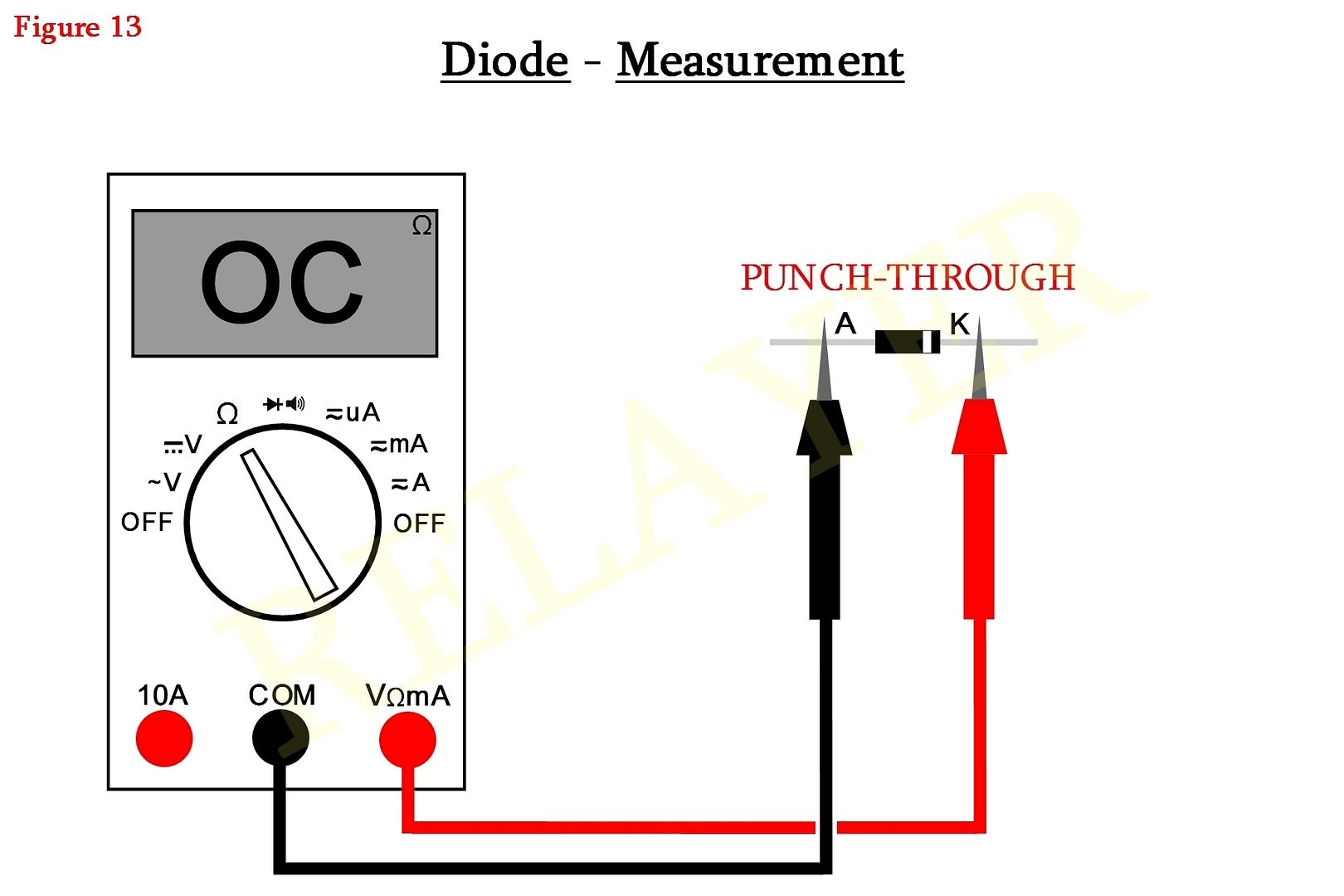
You should notice that the meter dial has been changed to the 'ohms' range.
We are now going to perform what they call a "Punch-through" test.
This tests the diode for reverse leakage via resistance. Since the ohms range is designed to place a slightly higher voltage across a component, its a good way to be doubly sure its not leaky. In most cases you should get an open-circuit condition.
Zener diodes can be an exception, same as when doing a reverse bias test with the meter selected for diode testing. Anything from a 4.7 volt zener or lower will show supposed leakage. But should be ok. Though if you're ever in doubt, replacement would be the best course of action.
That's it for now guys, sorry.
As I said at the start, when health permits, I'll continue on with transistor, voltage and current tests, and perhaps a bit more.
As with ALL tutorials there will be errors, omissions and mistakes, so feel free to please let me know in a positive way.
If you have any queries or questions, then please post them in this thread. I won't answer anything pertaining this tutorial privately, unless there are corrections to be made.
If you want this entire tutorial and associated pictures for personal viewing, then just PM me with your email address and I'll send you a zipped file with everything inclusive. DO NOT post your email address in the Forum threads. Not unless you want to cop mega spam in your IN box.
By the way, I don't mind if you use this or part of this tutorial on another website, provided you get permission from the Electronics One website.
If permission is granted, then using any part of this, you must mention it was obtained from the Electronics one Forum and done by myself, "Relayer". Please give credit where credit is due, that's all I ask. Thank you.
Regards,
Relayer
