Logic gates / counter help/ :{
Hey guys,
I Really hope you could help / advice me with my project.
My project is to create a car that will pass thru 9 stations overhead bridges. The car has a LDR on the top. The car will start at
station 1 and pass thru till station 9. When the car passes thru each station, it will count up till 9 (getting trigger signal from
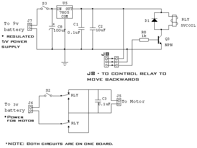
the LDR). Once it reaches station 9, it will send a signal to the motor driver circuit (See picture (Pin J8 connected to a relay))
which will cause the car to reverse and it will need to countdown as goes back to station 1.
I have the following circuit’s boards:
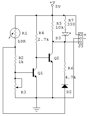
LDR Circuit
http://farm7.static.flickr.com/6229/627 ... 4f15be.jpg
Motor Driver & Power supply (9V to 5V)
http://farm7.static.flickr.com/6112/627 ... fa1b_b.jpg
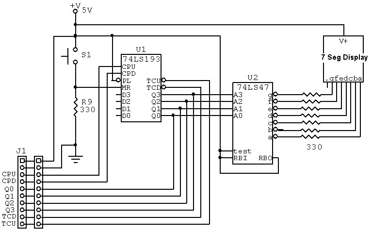
UP/DOWN Counter (74LS193) to BCD (74LS47) to 7 Seg display
http://farm7.static.flickr.com/6232/627 ... 0d39_b.jpg
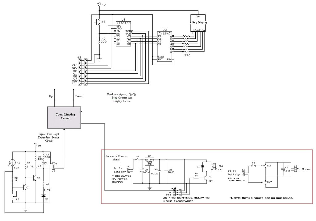
Here is the overview picture of the whole circuit:
http://farm7.static.flickr.com/6114/627 ... a90b_b.jpg
[u]The above circuits have been given, i will need to design a "c0unting limiting circuit" which will act as the brain of the car.[/u]
The components I can use are:
74LS32 OR gate
74LS08 AND gate
74LS04 NOT gate
74LS02 NOR gate
74LS00 NAND gate
74LS74 D flip flop
2N3904 NPN transistor
I hope and appreciate you are able to help as i really lost. Thanks alot!!!
Electronics Forum
Electronics Circuits & Projects discussion forum. Get help with electronics.
Logic gates / counter help/ :(
Moderator: pebe
2 posts
• Page 1 of 1
Logic gates / counter help/ :(
![]() by wiztaylor » Wed Oct 26, 2011 10:04 am
by wiztaylor » Wed Oct 26, 2011 10:04 am
- wiztaylor
- Posts: 1
- Joined: Wed Oct 26, 2011 9:58 am
![]() by Thomas W » Thu Oct 27, 2011 5:23 pm
by Thomas W » Thu Oct 27, 2011 5:23 pm
Your car can be in 18 different states:
1. Heading for bridge 1, driving forward.
...
9. Heading for bridge 9, driving forward.
10. Heading for bridge 9, driving in reverse.
...
18. Heading for bridge 1, driving in reverse.
You'll need a 6 bit memory to be able to represent 18 different states.
1 flip flop is 1 bit.
Draw a state diagram: http://en.wikipedia.org/wiki/State_diagram
An output from the Count Limiting Circuit should be connected to J8 pin 3.
- Thomas W
- Posts: 51
- Joined: Wed Sep 21, 2011 6:12 am
- Location: Silkeborg, Denmark
2 posts
• Page 1 of 1
Who is online
Users browsing this forum: No registered users and 3 guests
 |
Powered by phpBB® Forum Software © phpBB Group