Electronics Forum

Electronics Circuits & Projects discussion forum. Get help with electronics.


LED Roulette Help (Sim & Breadboard)

Discuss about electronic circuits here. Request help for circuits that you couldn't find anywhere else, how a circuit works etc. Discuss anything related to electronic circuits.

Moderator: pebe

LED Roulette Help (Sim & Breadboard)

Postby RuairiMonahan » Sun Jan 03, 2016 11:45 pm

Hello everyone,
This is my first post and hopefully not my last as I hope to reply and help those in need as I expand my own knowledge on circuitry (beyond that of fallout 4!). I have posted already on another website already.
I have a project which is due in a few weeks time (fast tracked course as we only received the assignment recently) and for my project I have chosen an LED roulette wheel with touch sensitive switch, which when triggered will produce the LEDs to light up one after the other until it stops on one random LED. I have researched several circuits (creating all of them on MultiSIM, which none of them worked exactly) and decided to focus on one particular circuit as I had the most success using MultiSIM (The LEDs spun once and the circuit crashed).
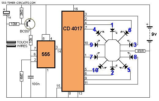
Imagehttp://www.555-timer-circuits.com/images/Roulette.gif
The above circuit is the one I chose. As this is a BTEC I cannot ask for help from the tutor however I am stuck in the mud right now (and usually I am quite good at building circuits both virtually and practically) as I cannot get the virtual simulation to work but more importantly I cannot get the circuit to work on a breadboard. Does anyone have any suggestions? I would really appreciate some help here and even a diagram of the breadboard just to help would be great also! Obviously I do not want someone else to do my project for me however a diagram or two would really help me as I am quickly running out of ideas and who better to ask than the experts?
RuairiMonahan
 
Posts: 1
Joined: Sun Jan 03, 2016 11:33 pm

Re: LED Roulette Help (Sim & Breadboard)

Postby Relayer » Mon Jan 04, 2016 9:21 am

Hello RuairiMonahan,
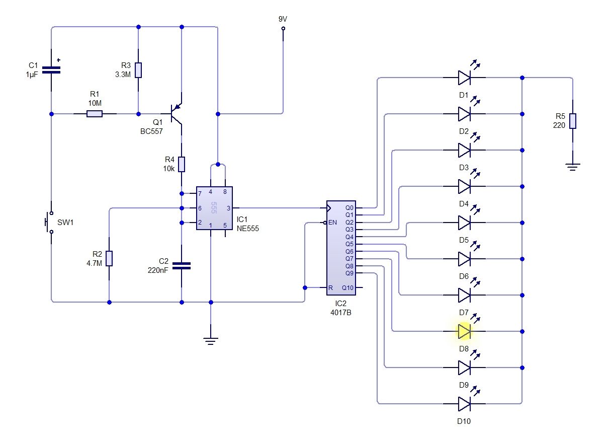
I did a mock up of the circuit you posted using Circuit Wizard 2 and it worked quite well. Though not in a pinwheel arrangement. Check the picture below:

Image

One main problem with using either a 4017 or 4022 is their woeful pin-out arrangement. I try avoiding doing any circuits with either two of the Decade or divide-by-eight Counters. I think they were designed by a monkey or they are strictly to be used on double sided PCB's. They are a nightmare to wire on anything single-sided: PCB, Breadboard etc...
Do you have to do your project on the 4017, or can you use something else? Say a LM3914 10 LED Dot/Bar Display Driver IC instead?
Regards,
Relayer

EDIT: You may notice I changed the values of C2 and R5. I upped C2's value to minimize the length of time of the pinwheel slowdown. I changed R5 to a lower value to make my LED's a tad brighter. But using the values in your diagram it worked fine.
Relayer
 
Posts: 33
Joined: Sat Sep 12, 2015 12:50 am
Location: Werribee. Australia


Return to Electronic Circuits Help


Who is online

Users browsing this forum: No registered users and 9 guests


cron