by pebe » Sat May 24, 2014 3:28 pm
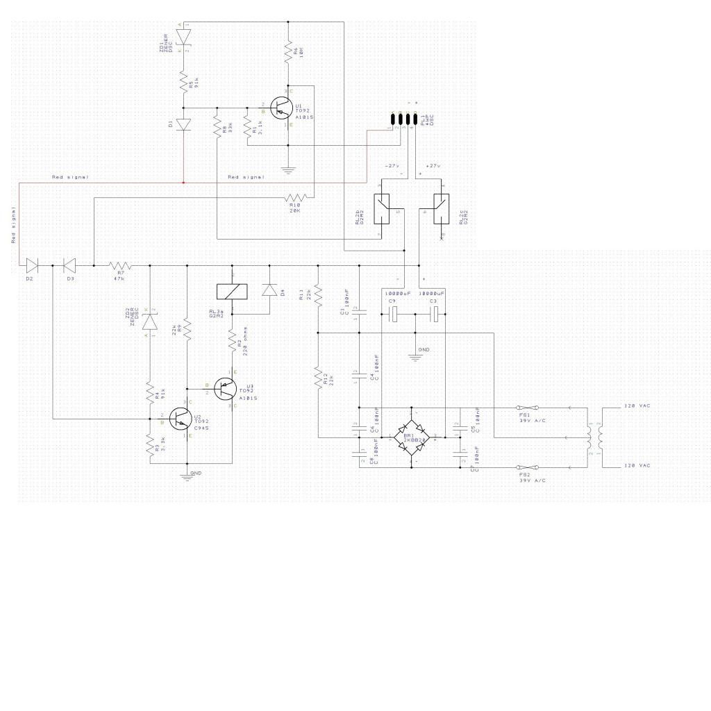
Are you sure you have drawn the circuit correctly, because there are a couple of anomalies. The drawing is in .jpg format so numbers and lettering are fuzzy, but I hope I have read them right.
Let’s look at the power supply first. Both inputs are marked 12V, so I assume the supply voltage is 12VAC. If so, C2 and C3 between them will charge to peak supply voltage less the voltage drop of two diodes in the bridge rectifier = (12V x 1.4) – 1.3V = 15.5V. R11 and R12 define the ground potential relative to the + and – rails. As they are both equal value at 10K, then the ground potential is midway between the two rails, ie. the DC supply is +7.75V and –7.75V. (Note that C2 and C3 are shown with wrong polarities).
There is bias through Z02 and the 10K so U2 and U3 are conducting and the relay is energised. But with both associated diodes having their cathodes to the base of U2, there is no way that the relay can be turned off.
There is a problem because the relay current must pass from the DC+ rail to ground and through R12 to the DC- rail. So the resistance of the relay plus R2 (probably about 150ohms) is now effectively in parallel with R11 which will shift the ground potential relative to the two power rails. DC+ will decrease and DC- will increase, although the difference between them will still be 15.5V. The results of that are unpredictable.
I assume the relay contacts are shown in the normal relay-off position, so as soon as the relay switches on, the DC-line biases on U1 via R8. But nothing in that part of the circuit or a pulse from the red line can turn off U2 and the relay, so I cannot see how the circuit, as drawn, can work.