Electronics Forum

Electronics Circuits & Projects discussion forum. Get help with electronics.


help with how this works please

Discuss about electronic circuits here. Request help for circuits that you couldn't find anywhere else, how a circuit works etc. Discuss anything related to electronic circuits.

Moderator: pebe

help with how this works please

Postby Keshka » Sat May 24, 2014 5:07 am

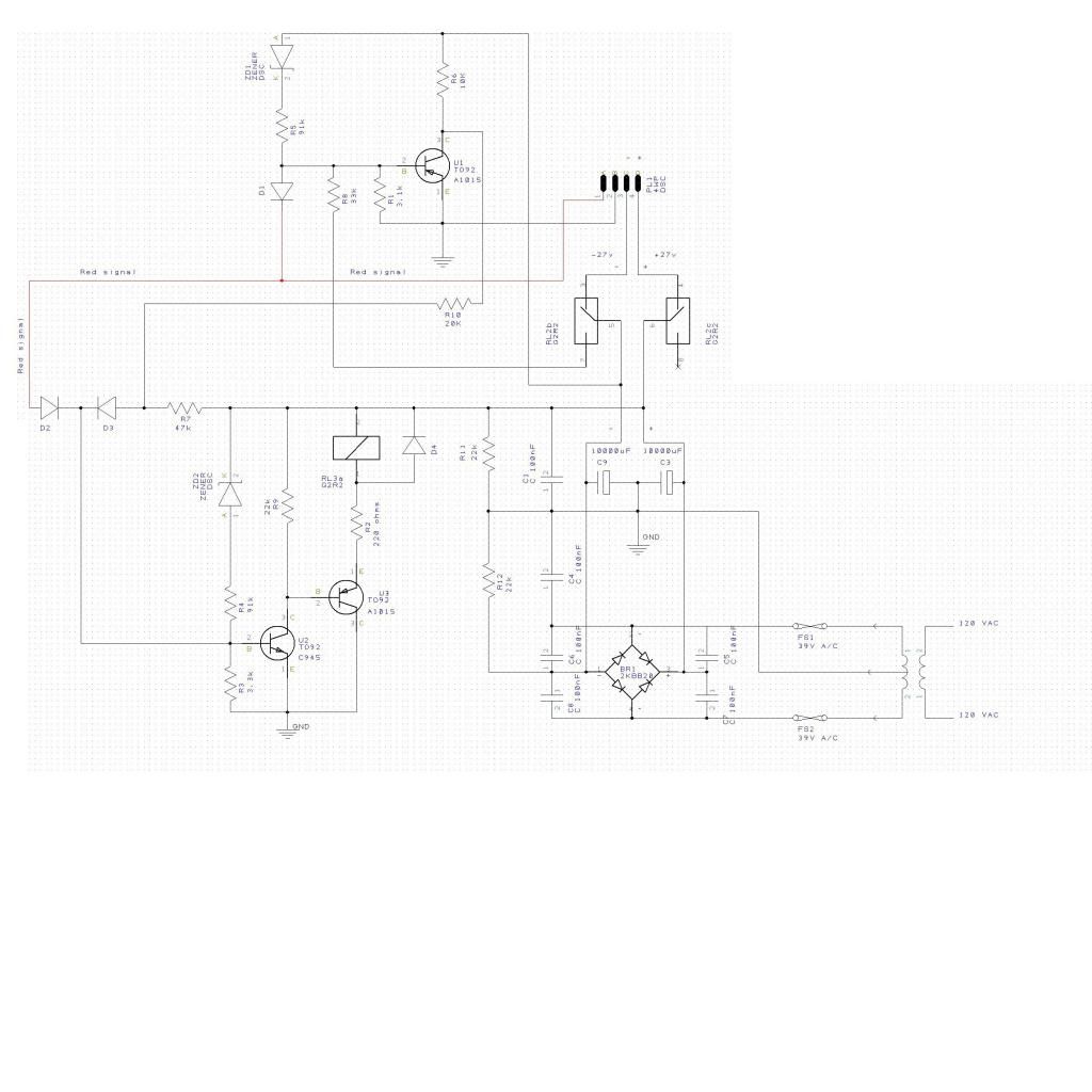
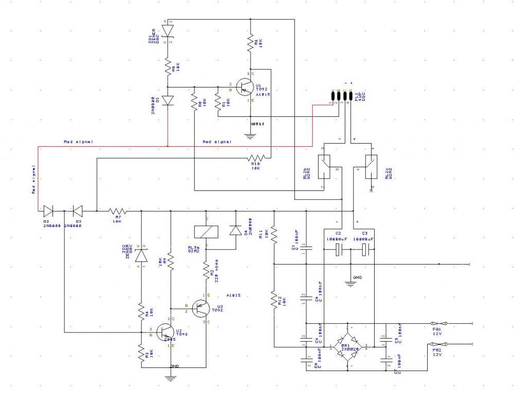
The schematic below is one I have drawn from a board that is malfunctioning. Please note, few of the component values listed are correct. I can if needed get values for all the caps and resistors.

I believe this to be some sort of latching relay circuit. The plus and minus voltages from the bridge are about +12v, ground, -12v.

The transistor numbers are correct.

what I would like to know is what the input signal should look like. It is the red wire.

Thank you
Keshka
Image
Keshka
 
Posts: 2
Joined: Sat May 24, 2014 4:52 am

Re: help with how this works please

Postby pebe » Sat May 24, 2014 3:28 pm

Are you sure you have drawn the circuit correctly, because there are a couple of anomalies. The drawing is in .jpg format so numbers and lettering are fuzzy, but I hope I have read them right.

Let’s look at the power supply first. Both inputs are marked 12V, so I assume the supply voltage is 12VAC. If so, C2 and C3 between them will charge to peak supply voltage less the voltage drop of two diodes in the bridge rectifier = (12V x 1.4) – 1.3V = 15.5V. R11 and R12 define the ground potential relative to the + and – rails. As they are both equal value at 10K, then the ground potential is midway between the two rails, ie. the DC supply is +7.75V and –7.75V. (Note that C2 and C3 are shown with wrong polarities).

There is bias through Z02 and the 10K so U2 and U3 are conducting and the relay is energised. But with both associated diodes having their cathodes to the base of U2, there is no way that the relay can be turned off.

There is a problem because the relay current must pass from the DC+ rail to ground and through R12 to the DC- rail. So the resistance of the relay plus R2 (probably about 150ohms) is now effectively in parallel with R11 which will shift the ground potential relative to the two power rails. DC+ will decrease and DC- will increase, although the difference between them will still be 15.5V. The results of that are unpredictable.

I assume the relay contacts are shown in the normal relay-off position, so as soon as the relay switches on, the DC-line biases on U1 via R8. But nothing in that part of the circuit or a pulse from the red line can turn off U2 and the relay, so I cannot see how the circuit, as drawn, can work.
pebe
 
Posts: 1058
Joined: Tue Dec 09, 2003 11:12 pm
Location: Ellon, Scotland

Re: help with how this works please

Postby Keshka » Mon Jun 09, 2014 5:23 am

Image

Here is an updated drawing at a higher resolution. I have added component values and measured voltages.
The relay contacts are shown in the de-energised position. The 39vac is across the both secondaries or half that from the center tap.

Thank you for your reply Pebe. Perhaps my updates will help. The system in it's normal state upon applying power, has the relay de-energised so I am guessing some signal on the red wire triggers the "latch", engaging the relay and locking it such that only a power down will reset it. I am guessing this is normal operation. So the only question I am left with is what polarity and perhaps voltage would be required to "trip" this system.

Keshka
Keshka
 
Posts: 2
Joined: Sat May 24, 2014 4:52 am

Re: help with how this works please

Postby pebe » Thu Jun 12, 2014 12:57 pm

The connection now added between ground and the transformer CT answers my power supply query. But your drawing is still in .JPEG instead of in .GIF which would have been much clearer, and I am uncertain whether the bottom of R1 is connected to ground, because the intersecting lines are fuzzy.

The top transistor (U1?) is an NPN one whereas its collector is supplied from the negative rail, so that part of the circuit doesn't make sense. Can you clarify?
pebe
 
Posts: 1058
Joined: Tue Dec 09, 2003 11:12 pm
Location: Ellon, Scotland


Return to Electronic Circuits Help


Who is online

Users browsing this forum: No registered users and 20 guests


cron