Electronics Forum

Electronics Circuits & Projects discussion forum. Get help with electronics.


output with short cirquit protection and current limiter

Discuss about electronic circuits here. Request help for circuits that you couldn't find anywhere else, how a circuit works etc. Discuss anything related to electronic circuits.

Moderator: pebe

output with short cirquit protection and current limiter

Postby silvio1234 » Wed May 07, 2014 7:46 am

Hello all,

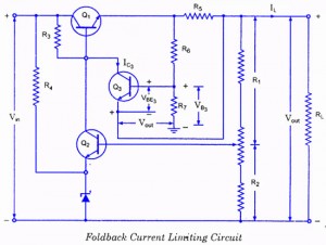
can anybody show me how to improve the following circuit for the following needs:
- input voltage should be 12 V
- output voltage @ < 50 mA should be near 12 V (low drop out)
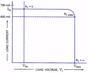
- very sharp current limiter curve
- the circuit should cut very sharp at 50 mA
- short circuit protection

My idear was to use anything like a TL431 with its very sharp curve to improve the circuit.

Any ideas? :?:
Image Image

Thanks,
silvio1234
 
Posts: 7
Joined: Wed May 07, 2014 7:33 am

Re: output with short cirquit protection and current limiter

Postby pebe » Thu May 08, 2014 10:55 am

Maybe this will do what you want.

To set up, turn P1 to the end where T1 is cut off.
Then turn P1 till you get 50mA output.
Attachments
Current-Limiter.GIF
Current-Limiter.GIF (3.37 KiB) Viewed 20185 times
pebe
 
Posts: 1058
Joined: Tue Dec 09, 2003 11:12 pm
Location: Ellon, Scotland

Re: output with short cirquit protection and current limiter

Postby silvio1234 » Thu May 08, 2014 1:32 pm

Thank you very much.

is it possible to put the 1R sense resistor to the positive power path near +Out?
I like to have a common 0V at input and output side.

Silvio
silvio1234
 
Posts: 7
Joined: Wed May 07, 2014 7:33 am

Re: output with short cirquit protection and current limiter

Postby silvio1234 » Thu May 08, 2014 2:15 pm

Hello pebe,

i tested the circuit with the result that the output is 0 V and there is no setup by the trim pot.
The output of the OpAmp does not change by setup the trim pot.

Any ideas?

Silvio.
silvio1234
 
Posts: 7
Joined: Wed May 07, 2014 7:33 am

Re: output with short cirquit protection and current limiter

Postby silvio1234 » Thu May 08, 2014 2:43 pm

It seems that the offset pins are not simulated with PSpice. So Il like to
solder this circuit.

Silvio.
silvio1234
 
Posts: 7
Joined: Wed May 07, 2014 7:33 am

Re: output with short cirquit protection and current limiter

Postby silvio1234 » Thu May 08, 2014 6:45 pm

Hello pebe,

I built up the circuit, but the ouput of opamp is always powered to nearly 12 V.
Nohing happens if I put one of the offset inputs to 0V.

Any ideas?

Silvio.
silvio1234
 
Posts: 7
Joined: Wed May 07, 2014 7:33 am

Re: output with short cirquit protection and current limiter

Postby pebe » Fri May 09, 2014 8:25 am

Although I haven't tried this circuit, I have done many similar ones. The CA3140 will run with its inputs down to the negative supply rail, and the trimpot should alter the relative input voltage offsets so the output can be set high or low when both inputs are the same.

But I will change the arrangement when I draw up an alternative circuit with the sensing resistor in the +supply, as you wanted.

(Edit). I cannot see how you get nearly 12V from the op-amp output - the data sheet gives a maximum of only about Vs minus 2V (10V) - hence the need for the potential divider R1/R2 on the base of T1.
pebe
 
Posts: 1058
Joined: Tue Dec 09, 2003 11:12 pm
Location: Ellon, Scotland

Re: output with short cirquit protection and current limiter

Postby pebe » Fri May 09, 2014 10:19 am

Here is a modified circuit with R3 in the positive output lead.

The dividers R4 to R7 are necessary because the 3140 inputs cannot be taken up to the positive rail. If you can find a suitable op-amp with rail-to-rail inputs and offset nulling capability, then you can get rid of the dividers and wire the inputs direct to R3.

If the op-amp also has a rail-to-rail output then you can get rid of R1.
Attachments
Current-Limiter 2.GIF
Current-Limiter 2.GIF (3.66 KiB) Viewed 20161 times
pebe
 
Posts: 1058
Joined: Tue Dec 09, 2003 11:12 pm
Location: Ellon, Scotland

Re: output with short cirquit protection and current limiter

Postby silvio1234 » Fri May 09, 2014 11:45 am

Thank you very much for this concept.
I'll test it.

Silvio.
silvio1234
 
Posts: 7
Joined: Wed May 07, 2014 7:33 am

Re: output with short cirquit protection and current limiter

Postby silvio1234 » Fri May 09, 2014 9:40 pm

Well I tested it but the output is always 0V because the opamp out is 11,5V and so
the transistor opens. Both inputs of opamp are nearly 0mV.
It needs a path from circuit input side to opamp inputs to make a voltage diffrence between both inputs and so a level change for swiching the transistor into on state.

Silvio.
silvio1234
 
Posts: 7
Joined: Wed May 07, 2014 7:33 am

Re: output with short cirquit protection and current limiter

Postby pebe » Sat May 10, 2014 8:42 am

Oops! I should have given it more thought. No output voltage - no nulling.

This revised circuit should do it, though I cannot understand why the nulling pot did not work before. Page 8 of the CA3140 Intersil data sheet from this site gives details of offset nulling and shows that the pot on its own is more than adequate - indeed, it suggests padding resistors may be required.

http://www.datasheetcatalog.com/

One reservation I have is that as the output voltage falls as T1 cuts off, the input voltage range will also fall and I am not sure that the input offset voltage will not change as the inputs go from about 8V down to zero. If it does, then it may be necessary to provide some hysteresis. I much prefer my first circuit where the situation does not arise.
Attachments
Current-Limiter 3.GIF
Current-Limiter 3.GIF (3.87 KiB) Viewed 20082 times
pebe
 
Posts: 1058
Joined: Tue Dec 09, 2003 11:12 pm
Location: Ellon, Scotland


Return to Electronic Circuits Help


Who is online

Users browsing this forum: No registered users and 9 guests


cron