Electronics Forum

Electronics Circuits & Projects discussion forum. Get help with electronics.


MAINS LED - design issue

Discuss about electronic circuits here. Request help for circuits that you couldn't find anywhere else, how a circuit works etc. Discuss anything related to electronic circuits.

Moderator: pebe

MAINS LED - design issue

Postby sargan » Thu Jan 30, 2014 11:14 am

Creating new topic as the Q is different.

I have a need to display ON condition of 19 mains signals (heating system)
Zone valves, Boiler, pump etc.
I can get the 220V 'ON' for each part easily enough .... want a simple way to have an LED indicate state ... illuminated = ON
After a lot of Googling around found

http://www.marcspages.co.uk/tech/6103.htm

in particular the cct:
Image


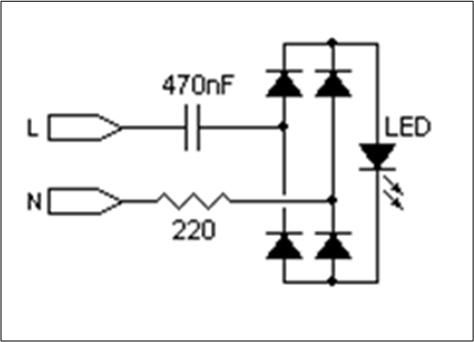
However this cct seems to be flawed.
The in-rush current is ~1.5A and blows the LED's
The LED current should be limited to 20mA

I have purchasde the diode bridges, LED & Capacitors.
W10 Bridge recifiers
LED are standard 5mm LED (100mcd) ... forward Voltage 1.8-2.2V
Capacitors are 0.47uF Polypropylene X2 series rated for 240V AC use


The purpose of series resistor is to limit the inrush current (and suppress harmonics)if the circuit is energised when mains voltage is at peak, the capacitor will
momentarily behave like a short circuit. The 220ohm will result in 1.5A through the LED - built a test cct and they are failing.

Could someone knowledgeable take a look and see how I can make this work .... no resistors bought yet .... but having bought the LED, Rectifiers & capacitors keen to use those.

I wanted to use the capacitor voltage drop approach to avoid using a resistor as voltage dropper, as heat dissipated is too high for 19 of them.
sargan
 
Posts: 16
Joined: Tue Jan 21, 2014 9:40 pm

Re: MAINS LED - design issue

Postby pebe » Thu Jan 30, 2014 2:30 pm

Are you sure it is the inrush current that is your problem? I have pulsed IR diodes at over 1A, at 10µs on and 1ms off, with no problems. The data sheet will normally specify how much over-current can be tolerated and for what time, provided the mean power dissipation is not exceeded.

I think it far more likely that the steady 32mA current obtained when using a 0.47µF capacitor is too much for the 20mA rated LED. I have encountered the same problem with some Chinese LEDs, where the stated current is the absolute max current..

You could prove a point by using two 0.47µF caps in series to get 18mA current. If that's OK I would change the .47µF to a .22µF cap to get 16mA. I usually aim for about 10- 12mA - that gives plenty of brightness.

Note that those currents are for 50Hz mains; with a .47µF cap you will be getting over 38mA if you are using 60Hz mains.
pebe
 
Posts: 1058
Joined: Tue Dec 09, 2003 11:12 pm
Location: Ellon, Scotland

Re: MAINS LED - design issue

Postby sargan » Thu Jan 30, 2014 3:04 pm

The LED data sheet states
1.8 - 2.1V fwd V
nominal fwd current 20mA
Max current 30mA

When I breadboarded cct .. they are drawing 31mA which is too high anyway ....
This is on UK 220V 50Hz
sargan
 
Posts: 16
Joined: Tue Jan 21, 2014 9:40 pm

Re: MAINS LED - design issue

Postby colin55 » Fri Feb 21, 2014 7:24 pm

Put one diode (in reverse) across the LED to prevent it blowing up.
colin55
 
Posts: 8
Joined: Sun Oct 27, 2013 8:05 am

Re: MAINS LED - design issue

Postby colin55 » Sat Feb 22, 2014 11:12 pm

Place a 1N4004 across the LED, but in reverse to the LED. Use 220n.
colin55
 
Posts: 8
Joined: Sun Oct 27, 2013 8:05 am

Re: MAINS LED - design issue

Postby sargan » Sun Feb 23, 2014 12:15 am

colin55 wrote:Place a 1N4004 across the LED, but in reverse to the LED. Use 220n.


Do to instability, I have now changed design to use mains neons instead ... no problem with current, no capacitor or diode Br needed.
sargan
 
Posts: 16
Joined: Tue Jan 21, 2014 9:40 pm


Return to Electronic Circuits Help


Who is online

Users browsing this forum: No registered users and 5 guests


cron