Electronics Forum

Electronics Circuits & Projects discussion forum. Get help with electronics.


Vero boarding

Discuss about electronic circuits here. Request help for circuits that you couldn't find anywhere else, how a circuit works etc. Discuss anything related to electronic circuits.

Moderator: pebe

Vero boarding

Postby sargan » Sun Jan 26, 2014 5:39 pm

It's been about 20 years since I did anything significant cct board manufacture, other than one or two components.

I have a small project where I will be interfacing 18 mains AC signals (220V) to a capacitor voltage drop cct to have an LED indicator for state of the mains (multi zone heating system)

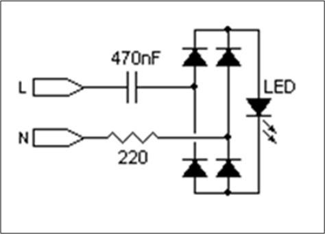
Decided on cct components, have tested via Breadboard and all works fine ...
(not very complex ... it's this x 18 using common N rail )
Image

Now in the past I have used Vero board and just drawn it out on graph paper, and then after a few attempts at layout on paper have created a board.

Obviously since my last creation PC's and software abound, is there any good free PC layout software for veroboard ? ... or is there a neater/better/simpler way to do this one off board.
It would seem uneconomic to create a pcb due to cost of etching materials.
Last edited by sargan on Sun Jan 26, 2014 6:15 pm, edited 1 time in total.
sargan
 
Posts: 16
Joined: Tue Jan 21, 2014 9:40 pm

Re: Vero boarding

Postby pebe » Sun Jan 26, 2014 6:01 pm

It says 'Image'. Should there be one?
pebe
 
Posts: 1058
Joined: Tue Dec 09, 2003 11:12 pm
Location: Ellon, Scotland

Re: Vero boarding

Postby pebe » Mon Jan 27, 2014 5:18 pm

It would be much simpler if you left out the 220Ω resistor and made the rectifier a half wave one, rather than full wave.

Do you want the LEDs as an 18way strip or a 9 x 2 oblong?
pebe
 
Posts: 1058
Joined: Tue Dec 09, 2003 11:12 pm
Location: Ellon, Scotland

Re: Vero boarding

Postby sargan » Mon Jan 27, 2014 5:31 pm

pebe wrote:It would be much simpler if you left out the 220Ω resistor and made the rectifier a half wave one, rather than full wave.

Do you want the LEDs as an 18way strip or a 9 x 2 oblong?


Tried it .... too much flicker on the LED, gone and bought a pack of 1.5A Bridge Rectifiers in RB-15 case style ...they were cheap enough.

I actually need 19 (miscounted) .... so Ideal layout would be 3 rows ... top 2 rows of 6 bottom row of 7

(edit) might actually be easier to have all the LED's mounted in pattern above on one board .... nice and easy, common anode rail etc. ... and have the other components on separate board ... probably help as well ... top board can bit fitted to project box lid ... while the 'power parts' board fitted to box base.
can use ribbon cable between them or similar
sargan
 
Posts: 16
Joined: Tue Jan 21, 2014 9:40 pm

Re: Vero boarding

Postby pebe » Mon Jan 27, 2014 6:47 pm

sargan wrote:... too much flicker on the LED, gone and bought a pack of 1.5A Bridge Rectifiers in RB-15 case style ...they were cheap enough.

I'm surprised. I have just finished a project that has 3 x 7seg displays multiplexed;at 8ms on and 16ms off (compared to your 10ms on and 10ms off) and there is no flicker.

I actually need 19 (miscounted) .... so Ideal layout would be 3 rows ... top 2 rows of 6 bottom row of 7

(edit) might actually be easier to have all the LED's mounted in pattern above on one board .... nice and easy, common anode rail etc. ... and have the other components on separate board ... probably help as well ... top board can bit fitted to project box lid ... while the 'power parts' board fitted to box base.
can use ribbon cable between them or similar

What spacing do you want between LEDs?
pebe
 
Posts: 1058
Joined: Tue Dec 09, 2003 11:12 pm
Location: Ellon, Scotland

Re: Vero boarding

Postby sargan » Mon Jan 27, 2014 7:46 pm

Not specific but if it was 25mm between centres then 2 x 6 and 1 x 7 row is going to fit neatly in the lid of a 175 x 100 project box
sargan
 
Posts: 16
Joined: Tue Jan 21, 2014 9:40 pm

Re: Vero boarding

Postby pebe » Tue Jan 28, 2014 10:52 am

OK. I'll do you a layout.
pebe
 
Posts: 1058
Joined: Tue Dec 09, 2003 11:12 pm
Location: Ellon, Scotland

Re: Vero boarding

Postby sargan » Tue Jan 28, 2014 11:26 am

excellent ...

In case its helpful .... I will use Bridge \Rectifiers instead of discrete diode ... W10 1.5A in Case Style RB-15

Capacitors are 0.47uF 250VAC 10% Polypropylene Safety Capacitor X2 (L*W*H) 13.8 x 9.9 x 1.5mm, lead spacing of 14.8mm
sargan
 
Posts: 16
Joined: Tue Jan 21, 2014 9:40 pm

Re: Vero boarding

Postby pebe » Tue Jan 28, 2014 5:03 pm

OK, here it is. I have arranged it at a 1" x 1" pitch as you requested.
I think it should be self-explanatory. If not, just shout.

Best of luck.
Attachments
LED Display.GIF
LED Display.GIF (11.95 KiB) Viewed 16730 times
pebe
 
Posts: 1058
Joined: Tue Dec 09, 2003 11:12 pm
Location: Ellon, Scotland

Re: Vero boarding

Postby sargan » Tue Jan 28, 2014 6:27 pm

Thanks a lot ... what program did you use ? good to know
sargan
 
Posts: 16
Joined: Tue Jan 21, 2014 9:40 pm

Re: Vero boarding

Postby pebe » Tue Jan 28, 2014 7:34 pm

No program. Done by hand.
pebe
 
Posts: 1058
Joined: Tue Dec 09, 2003 11:12 pm
Location: Ellon, Scotland

Re: Vero boarding

Postby sargan » Tue Jan 28, 2014 8:40 pm

pebe wrote:No program. Done by hand.


impressed
sargan
 
Posts: 16
Joined: Tue Jan 21, 2014 9:40 pm


Return to Electronic Circuits Help


Who is online

Users browsing this forum: No registered users and 25 guests


cron