Electronics Forum

Electronics Circuits & Projects discussion forum. Get help with electronics.


Multiple op amps in a circuit and split power supply

Discuss about electronic circuits here. Request help for circuits that you couldn't find anywhere else, how a circuit works etc. Discuss anything related to electronic circuits.

Moderator: pebe

Multiple op amps in a circuit and split power supply

Postby alkopop79 » Tue Nov 12, 2013 7:27 pm

Hi,


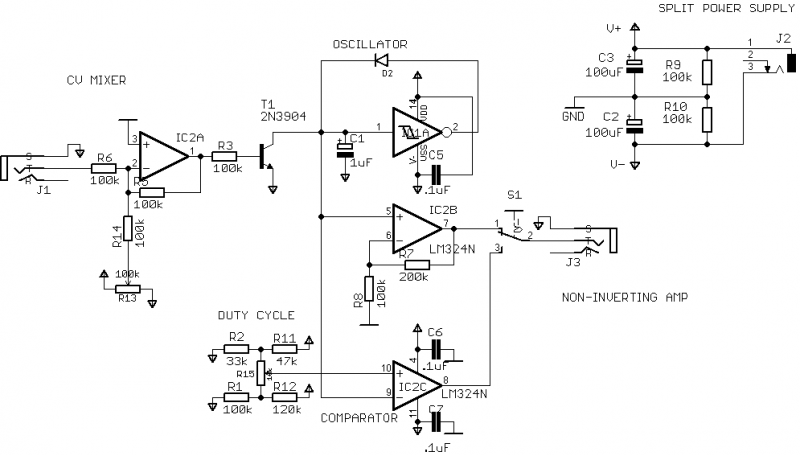
the circuit I've been having trouble with is a VCO (voltage controlled oscillator). It contains three op amp: a DC signal mixer, an amp (non-inverting) and a comparator. I wonder if I need a separate split power supply for each? The functional prototype works (it's a kludge) but this circuit will be manufacutred and I want to avoid any glitches. Also, are there any benefits of using a TLE2426 for virtual ground?

Image
alkopop79
 
Posts: 2
Joined: Tue Nov 12, 2013 7:17 pm

Re: Multiple op amps in a circuit and split power supply

Postby pebe » Wed Nov 13, 2013 5:24 am

You have not said what the problem is, or how the circuit is supposed to work.
I cannot see how the oscillator works or what the mixer is supposed to do.
You have not shown the power supply so I don't know if it will benefit from a TLE2426.
pebe
 
Posts: 1058
Joined: Tue Dec 09, 2003 11:12 pm
Location: Ellon, Scotland

Re: Multiple op amps in a circuit and split power supply

Postby alkopop79 » Wed Nov 13, 2013 8:31 am

You're right! The circuit is a voltage controlled oscillator for a synth. The circuit generates sawtooth wave using the 40106 inverter+capacitor combo. The sawtooth is then amplified IC2B. The op amp in the bottom is a comparator and it generates square wave from the sawtooth. Voltage (0-5V) is used to control the frequency of the oscillator. The CV (control voltage) comes from the mixer. The sources of CV are the potentiometer R13 and any voltage coming in through the socket J1. T1 transistor converts the control signal from linear to exponential. The split power supply in the upper-right corner is fed from the DC socket J2 and it provides virtual ground for the op amps. The circuit has been built and works but I wonder if it's worth using the TLE2426 instead of the resistors since it has a buffer?
alkopop79
 
Posts: 2
Joined: Tue Nov 12, 2013 7:17 pm

Re: Multiple op amps in a circuit and split power supply

Postby pebe » Thu Nov 14, 2013 10:57 am

You don't need to use a TLE242. You have a spare op-amp from the quad LM324, so you could use that to get a virtual ground with a low impedance output, like this. Get rid of C2 and C3 and feed the junction of R9/R10 to the non-inverting input of the spare amp. Connect the output to the inverting input and take that as the virtual ground.

BTW, the bridge around R15 could be simplified to two series resistors.
pebe
 
Posts: 1058
Joined: Tue Dec 09, 2003 11:12 pm
Location: Ellon, Scotland


Return to Electronic Circuits Help


Who is online

Users browsing this forum: No registered users and 8 guests


cron