Electronics Forum

Electronics Circuits & Projects discussion forum. Get help with electronics.


Air band Radio Receiver Circuits??

Discuss about electronic circuits here. Request help for circuits that you couldn't find anywhere else, how a circuit works etc. Discuss anything related to electronic circuits.

Moderator: pebe

Air band Radio Receiver Circuits??

Postby Happy_Jock » Sun Oct 06, 2013 7:34 pm

Hi folks, im still new to this forum, after some useful help on a circuit from Pebe, im very much impressed with the usefulness of this forum.

Ive been Building little circuits for a while now im still a newbie at the stage of understanding what each component is how the circuits are built, but still learning on the actual workings and value of the layout of circuits, I have built some sensors, amps, audio devices, and FM transmitters with gr8 success.

One idea that has fascinated me is the idea of building a receiver circuit for frequencies outside the normal commercial band 88 - 108 Mhz, for example a receiver that picks up civil air band 108-138Mhz or even military air band 230 - 420 Mhz.

I have searched the web time and time again with little success, when I do these searches, one Schematic keeps cropping up
Image

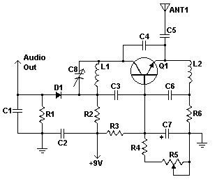
i had planed to build this in time when I have all the components, however a bit put of by comments stating some of those used in this circuit are hard to come by.

Im interested to know if this circuit looks accurate for use in the uk, and if anybody can tell me how difficult creating receivers for the above bands would actually be to build. My relatively tiny experience on RF circuits is making me assume if an FM or AM commercial band receiver can be created relatively easy, will one for different bands be much more difficult. ???

any info would be very useful

cheers
Happy_Jock
 
Posts: 22
Joined: Sat Oct 05, 2013 6:53 pm
Location: SCOTLAND

Re: Air band Radio Receiver Circuits??

Postby Happy_Jock » Mon Oct 07, 2013 2:29 pm

forgot to include the actual component list for the above schematic.. :roll:

R1, R3 2 47K 1/4W Resistor
R2 1 10K 1/4W Resistor
R4 1 4.7K 1/4W Resistor
R5 1 5K Linear Taper Pot
R6 1 2.2K 1/4W Resistor
C1, C2, C3, C6 4 x 0.001uF Ceramic Disc Capacitor
C4 1 2.2pF Ceramic Disc Capacitor
C5 1 1pF Ceramic Disc Capacitor
C7 1 15uF 15V Electrolytic Capacitor
C8 1 18pF Variable Capacitor
D1 1 1N82 Diode
Q1 1 2N918 NPN Transistor
L1 1 See Notes
L2 1 1.8uH Inductor
ANT1 1 Approx. 18 Inch Wire Antenna
MISC 1 PC Board, Wire, Knob For C8
Happy_Jock
 
Posts: 22
Joined: Sat Oct 05, 2013 6:53 pm
Location: SCOTLAND

Re: Air band Radio Receiver Circuits??

Postby pebe » Tue Oct 08, 2013 9:25 am

The circuit should be OK. All the parts are easily obtained, except perhaps the 2N918 - that’s a very old transistor. But you should find that the 2N3704 or something similar would be OK.

For working on other bands, have a look at this link. It uses a SA602 IC – also known as an NE602 or NE612 – as a frequency converter. You could buy a cheap transistor radio from Hong Kong for the receiver in place of the TCA440 IC. Then you are only concerned with changing the VCO for other bands.

http://hem.passagen.se/communication/118.html
pebe
 
Posts: 1058
Joined: Tue Dec 09, 2003 11:12 pm
Location: Ellon, Scotland

Re: Air band Radio Receiver Circuits??

Postby Happy_Jock » Wed Oct 09, 2013 10:22 pm

hi there pebe,

thanks for this link I like the look of that circuit, tell me if i wer to substitute the TCA440 with a cheap transistor radio, is there a particular type it must be, and am i correct in assuming that the radio will connect to the rest of the circuit directly after the mixer stage, and also become the source of audio output aswell ?

im deffo going to give this one a bash once i have tried the small schematic i posted.

ive had a bit of luck hunting down a few sources of the 2N918, was quite shocked it has 4 pins as oppose to the usual 3

the 1N82 germanium diode is the one im having a nightmare trying to find, so far the only info ive found as a suitable replacement is a 1N34. havent done to much work with diodes yet :|
Happy_Jock
 
Posts: 22
Joined: Sat Oct 05, 2013 6:53 pm
Location: SCOTLAND

Re: Air band Radio Receiver Circuits??

Postby pebe » Thu Oct 10, 2013 8:20 am

I have redrawn the circuit in a format that I can easily understand – rather than the haphazard way it was drawn. Now I can see it a TRF receiver with regeneration – not a super-regen receiver. I can see no way that D1 can conduct because to do so its cathode would have to go below the ground rail – and as a TRF it never will. Hence the circuit looks a bit ‘iffy’.

So unless you have already ordered the bits for it, I would suggest you to build this circuit instead, because its components will be less expensive and it will be easier to get going.

http://radiobuilder.blogspot.co.uk/2010 ... o-amp.html

Regarding the SA602, I’ll give more details in the next post.

BTW, in which part of Scotland do you live?
pebe
 
Posts: 1058
Joined: Tue Dec 09, 2003 11:12 pm
Location: Ellon, Scotland

Re: Air band Radio Receiver Circuits??

Postby pebe » Thu Oct 10, 2013 2:21 pm

Here is the datasheet for the SA602.

http://pdf.datasheetcatalog.com/datashe ... 691_DS.pdf


As you can see it is a mixer used for frequency changing. You put in two signals - the one you want (Fsig) and a local oscillator (Fosc). You then get two output frequencies, ie. Fsig + Fosc, and Fsig – Fosc. You can also use the oscillator so Fsig = Fosc, then you have a direct conversion (homodyne) receiver where the output is the audio signal that modulated Fsig and you only need an audio amp for the output.

There are two ways of using it as a frequency changer.
1. Feed in a tuneable oscillator as Fosc and output to a fixed frequency receiver or IF stage, or
2. Use a fixed Fosc and output to a tuneable receiver.

I think the second method is best because you don’t have to build a number of tuneable oscillators to cover the bands you want.

Looking on ebay for cheap receivers I saw this one

http://www.ebay.co.uk/itm/Portable-TV-F ... 3a690be661

I found this YouTube movie of someone using it.

http://www.youtube.com/watch?v=ahqvoeTaFPQ

It seemed to perform quite well and from the size and price, its component count must be minimal. Not surprising because I have a Chinese made mobile phone and the FM radio on that is superb. So I Googled for ‘chinese fm am receiver ic’ and came up with this

http://www.electronicspecifier.com/comm ... log-radios

and that may be the sort of IC that’s in it. Note the reference to the low component count in the second paragraph.

Now I am interested enough to have a go. So I ordered the radio, an SA602, and a 433MHz Tx/Rx pair (so I can use the Tx as Fosc) all for just over £7! Delivery is 2weeks, so then I’ll play!
pebe
 
Posts: 1058
Joined: Tue Dec 09, 2003 11:12 pm
Location: Ellon, Scotland

Re: Air band Radio Receiver Circuits??

Postby Happy_Jock » Fri Oct 11, 2013 5:56 pm

hi m8
im a born n bred edinbugger lol

thats a lot of info there im definitely going to try this circuit. im going to order the small hong kong radio and the chip, (actually interested just to see how this radio works on its own, Ive never really had use of a 12 band receiver). Im interested to hear your results so will be much appreciated if you keep me updated on how it goes. I still have a bit of reading and understanding exactly how it works before constructing it.

interesting to note, I had done a classic experiment i found on a site a few years back using a radio alarm clock, I opened up the clock and bend the radio circuit coils, as a result the radio then picked up a kind of Edinburgh airport weather report on repeat. this has left me very interested in the possibilities of modifying commercial band radios, so the method of using the hong kong radio seems exactly what iv been looking for.


in the mean time im going to make this small one. im about to draw up the PCB for this small Superregen Receiver in link you posted, I had actually already found this schematic and was deciding between this and the one with the dodge diode to construct, ill take your advice and stick with this one seems a lot easier as well.
Happy_Jock
 
Posts: 22
Joined: Sat Oct 05, 2013 6:53 pm
Location: SCOTLAND


Return to Electronic Circuits Help


Who is online

Users browsing this forum: No registered users and 17 guests


cron