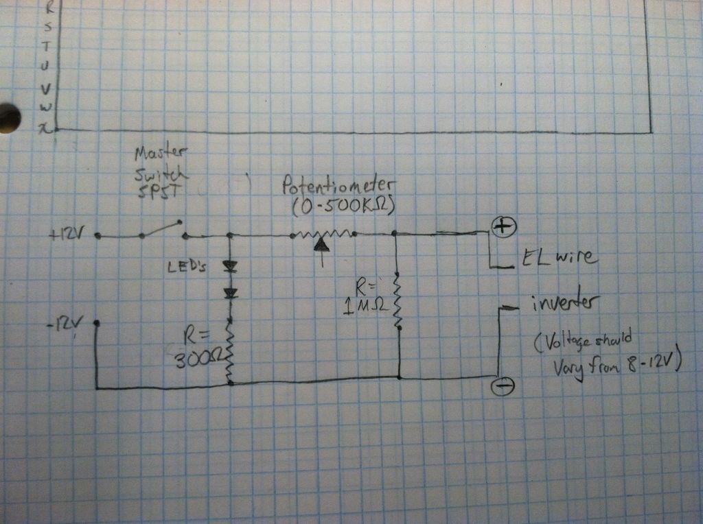
This is my first post to these forums and I'm requesting help with a circuit I am working on for an EL Wire dimmer. It's pretty basic and I am a novice so I may be making simple mistakes. Please bare with me
Here is the circuit I am trying to create. It takes a 12v DC input and powers 2 LED's. A voltage divider is then used (with a potentiometer) in an attempt to vary the voltage from 8-12v (lower input voltage to the EL Wire inverter yields a dimmer glow from the EL Wire).

I got this together on a breadboard and ran voltage through it using a power supply. I used a multimeter to measure output voltage as I varied the resistance using the potentiometer. Sure enough, it worked and the LED's remained constant brightness. Output voltage varied from 8-12v.
The varying output voltage powers an EL Wire inverter. This is where I ran into problems. When the output voltage of the circuit was used as the input voltage for the EL wire inverter the smooth variance from 8-12v was no longer present. Instead, voltage stayed at about 0.6v for most of the time and then, at a certain point of rotation of the potentiommeter, jumped up to 11-12v. Clearly the EL wire inverter is interacting in some way with my circuit that I am overlooking. Also, I've done a lot of soldering on the inverter board and ruined some things. To fix it I soldered around them and bypassed the "sound" part of the inverter so it is only constant on. Doing all of this may have messed something up with the inverter.
Extra info about the EL Wire inverter: [url="http://www.elwiresource.com/sound-activated/20-elwire-sound-inverter-26.html"]Here is a link to the one I am using[/url]. It's pretty common and available from a variety of online sites
More importantly, I know that is basically works by taking a DC input and making it an AC output which excites the phosphorous in the EL wire and makes it glow.
Thanks for baring with me through that and thanks very much to anyone that can help. I know it's a tall order and will probably require someone that understands EL Wire and/or EL Wire drivers to help answer my questions.

