Good morning E Zone,
http://www.youtube.com/watch?v=4pd6ih1C1kA
Finally got the PIR (passive infrared) motion detector to fire off a fairly intersting LED display without human intervention. The signal output of the PIR operates a five volt relay which is wired into a timer circuit by Vellmen called K2579. The relay output from
motion detector is employed as a substitute for the momentary trigger switch in the timer circuit.
It would be preferable to use a timer kit by Cana Kit called CK002, rather than Velleman K2579 because the Cana Kit is smaller
and cheaper.
Schematics:
http://www.allenpitts.com/electronics/5 ... 002_sm.jpg
http://www.allenpitts.com/electronics/5 ... 0001_e.jpg
But when the Can CK002 is subtituted for the Velleman K2579 the CK002 only operates for as long as the signal from the PIR, about two seconds.
In other words, when set for thirty seconds and connected to the G4765, the CK002 only stays on for two seconds. When set for thirty seconds and connected to the G4765, the the K2579 stays on for thirty seconds as intended.
I have studied the circuits for hours and have discovered several similarities. Pins six and seven of the 555 IC
are shunted and are connected to a pot to adjust the time of the output
in both circuits. Although the K2579 has momentary trigger
and reset switches the trigger switch, the trigger switch can be mimicked by quickly connecting and disconnecting the power to the CK002 and
the function of reset switch is obviated after the thirty seconds is up because the system has reurned to the original state.
In the CK002 pin 2 of the 555 is connected to ground thru a capacitor but in K2579 there is no capacitor between the IC pin 2 and ground.
In the K2579 pin 5 is connected toground thru a 10K resistor, R2 but in the CK002 circuit Pin 5 is connected to ground thru
a capacitor.
But thing thats really got me stumped is: What is the function of the transistor on the K2579?
How can I make the CK002 funtion like the K2579?
Thanks.
Allen in Dallas
Electronics Forum
Electronics Circuits & Projects discussion forum. Get help with electronics.
Motion detector fires off LED display
Moderator: pebe
7 posts
• Page 1 of 1
Motion detector fires off LED display
![]() by pittsallen@usa.net » Mon Jul 18, 2011 1:40 pm
by pittsallen@usa.net » Mon Jul 18, 2011 1:40 pm
- Attachments
-
- This is a diagram of the working system
- motion_detector_w_LED_display_c.gif (28.07 KiB) Viewed 24392 times
- pittsallen@usa.net
- Posts: 9
- Joined: Mon Jul 18, 2011 1:13 pm
![]() by pebe » Mon Jul 18, 2011 4:00 pm
by pebe » Mon Jul 18, 2011 4:00 pm
Hi Allen,
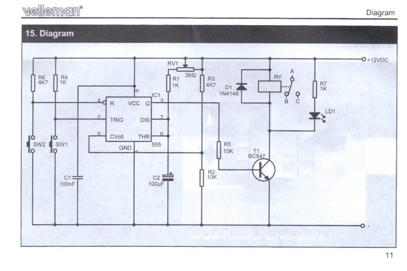
The CK002 will not work as it is wired now. Pin 4 is the reset pin and must not be left unconnected. If you want a reset then copy R6 and SW2 from the Velleman circuit. If not, just connect pin 4 to Battery+.
In the CK circuit C3 must be removed and the connections from your relay contacts wired in its place. Closing the contacts will start the timer. Assuming that the time constants in both circuits are the same, ie. (RV1+R1) x C2 in the Vellerman = (P1+R1) x C1 in the CK002, then you will get the delay you want.
In the Vellerman circuit, R3 and R2 put +8v on to pin 5. They are unnecessary because pin 5 is already fed with 8V internally. Vellerman probably fitted them for some other application, but they are certainly not needed here. In the CK circuit you can leave out C2 and leave pin 5 unconnected. I have wired dozens of 555s and never found C2 necessary.
Re your query about the transistor T1. This is to provide power to operate the relay. Vellerman have probably done that for safety, because they don't know the type of relay that the user will fit. But the 555 can provide 200mA from pin 3 and that's enough for all normal relays. So the output circuit of the CK002 is quite OK.
I hope that helps.
- pebe
- Posts: 1058
- Joined: Tue Dec 09, 2003 11:12 pm
- Location: Ellon, Scotland
![]() by pittsallen@usa.net » Mon Jul 18, 2011 4:29 pm
by pittsallen@usa.net » Mon Jul 18, 2011 4:29 pm
Good morning Pebe,
Thanks for your excellent reply.
The answers to both questions are complete and understandable even to a relative newbie like myslf who has limited knowledge of electronics engineering. (I have posted questions to several other electronics forums [All About Circuits]. The replies seemed to be aimed at more at advertising how smart the answer author was than explaining the concepts to an admitted ignorant who sincerely seeks knowledge.)
Unfortunately I am a working stiff who has limited time during the week to experiment with electronic circuits. That is why my questions are usually spawned on the weekend or Monday morning. It will be next weekend until I have a chance to implement your excellent counsel. But I will reply with the results of the trials next weekend. Until then I remain
Sir,
Your grateful servant
Allen Pitts, Dallas Texas
- pittsallen@usa.net
- Posts: 9
- Joined: Mon Jul 18, 2011 1:13 pm
![]() by pebe » Mon Jul 18, 2011 7:22 pm
by pebe » Mon Jul 18, 2011 7:22 pm
Hi Allen,
I'm glad you found it useful. You can find out more about the 555 here
http://www.kpsec.freeuk.com/555timer.htm
From your diagram, it looks like you are using it to drive a 4017 counter. But if you are going to drive a relay then note the section about fitting a diode across it.
Have fun.
I'm glad you found it useful. You can find out more about the 555 here
http://www.kpsec.freeuk.com/555timer.htm
From your diagram, it looks like you are using it to drive a 4017 counter. But if you are going to drive a relay then note the section about fitting a diode across it.
Have fun.
- pebe
- Posts: 1058
- Joined: Tue Dec 09, 2003 11:12 pm
- Location: Ellon, Scotland
![]() by pittsallen@usa.net » Sat Jul 23, 2011 9:24 pm
by pittsallen@usa.net » Sat Jul 23, 2011 9:24 pm
Good afternoon Pebe,
Well its Saturday and I get to work on my circuits.
In order to understand the Cana Kit CK002 I drew a picture
of a combination of the traces and the components
http://www.allenpitts.com/electronics/5 ... line_b.jpg
Then using your excellent suggestions I changed the
circuit
http://www.allenpitts.com/electronics/5 ... hacked.jpg
The main idea is I am using a PIR (passive infrared detector) to activate an LED display.
http://www.goldmine-elec.com/pdf/G4567.pdf
The PIR signal ony lasts two seconds. So the G4567 should trigger a tmer circuit, the CK002, to operate a relay that controls the power source to the LED display.
The problem is CK002 only stays on as long as it gets power. I think the problem is that the CK002 system needs power but that power should be
separate from the signal to pin two (trigger) of the timer. That is, the CK002 gets power all the time but the power to the trigger pin would only
be applied by a moomentary switch in test and by the G4567 in the final system.
So I changed the circuit
http://www.allenpitts.com/electronics/5 ... hacked.jpg
First I added J1 which connects pin 4 of the 555 to the 9 volt power source according to the suggestion to connect the reset poin of the 555 to the power source.
Then I added J2 so the LED would work.
I reasoned that when R2 was disconnected the connection to the trigger would be lost and and a momentary switch between R2 and the trace to the trigger pin would act as a trigger. So I could leave the power connected to the CK001 system but the trigger which fires the timer and the relay would only be activated by pushing the momentart switch.
But it disn't work as expected. The system stills stays on as long as the
battery contacts are connected. Also I must have caused a short to the LED because seems to have fried.
So I tried several different configurations with no luck. But in the process
of trying different wirings, with J2 connected to the positive end of the LED and the other end of J2 disconnected, I accidently touched the non LED end of J2 to connection point marked pcb1 that is connected to the trace that leads to pin 2, the trigger of the 555. The circuit acted as required for several cycles and I was thinking about connecting a momentary switch
or the signal from the PIR between pcb1 and the anode of the LED.
But then circuit quit working and I am back to square one.
Any ideas what I am doing wrong?
I have not tried to connect the diodes across the output because I got
involced in the trigger problem before I got to the diodes.
Thanks.
Allen in Dallas
- Attachments
-
- CK002_composite_line_hacked.jpg (81.69 KiB) Viewed 24378 times
-
- CK002_composite_line_b.jpg (80.13 KiB) Viewed 24378 times
- pittsallen@usa.net
- Posts: 9
- Joined: Mon Jul 18, 2011 1:13 pm
![]() by pebe » Sun Jul 24, 2011 11:36 am
by pebe » Sun Jul 24, 2011 11:36 am
Hi Allen,
When I said "In the CK circuit C3 must be removed and the connections from your relay contacts wired in its place", I meant the contacts of the 5V relay operated by the PIR detector in your first posting. They trigger the timer.
Here is how it should be wired. Connect up the diode as shown if you are going to drive a relay with the timer.
- Attachments
-
- 555 board.GIF (57.52 KiB) Viewed 24371 times
- pebe
- Posts: 1058
- Joined: Tue Dec 09, 2003 11:12 pm
- Location: Ellon, Scotland
![]() by pittsallen@usa.net » Fri Jul 29, 2011 2:40 pm
by pittsallen@usa.net » Fri Jul 29, 2011 2:40 pm
Good morning Pebe,
Getting ready for Saturday. Thanks for your reply, especially taking time to mark up the PCB image. Just to make sure I have it right, I have redone the diagram of the overall system and added reference points on the PCB diagram that refer to hook up points on the system diagram.
Thanks again.
Allen in Dallas
- Attachments
-
- Pebe's_555_110728.jpg (142.06 KiB) Viewed 24365 times
-
- Revised PIR Motion Detector, Timer, LED Display
- PIR_Motion_Detector_Timer_LED_Display_110729.jpg (45.7 KiB) Viewed 24365 times
- pittsallen@usa.net
- Posts: 9
- Joined: Mon Jul 18, 2011 1:13 pm
7 posts
• Page 1 of 1
Return to Electronic Circuits Help
Who is online
Users browsing this forum: No registered users and 11 guests
 |
Powered by phpBB® Forum Software © phpBB Group